


Teledyne API – T101 Operation Manual Getting Started
33
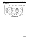
3.3. ELECTRICAL CONNECTIONS
NOTE
To maintain compliance with EMC standards, it is required that the cable length be no greater than
3 meters for all I/O connections, which include Analog In, Analog Out, Status Out, Control In,
Ethernet/LAN, USB, RS-232, and RS-485.
CAUTION
Check the voltage and frequency label on the rear panel of the instrument for
compatibility with the local power before plugging the T101 into line power.
Do not plug in the power cord if the voltage or frequency is incorrect.
CAUTION
Power connection must have functioning ground connection. Do not defeat the ground
wire on power plug.
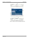
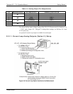
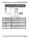
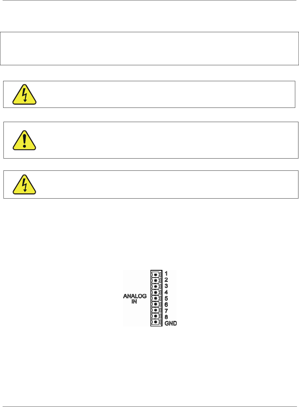
3.3.1. ANALOG INPUTS (OPTION 64) CONNECTIONS
The Analog In connector is used for connecting external voltage signals from other
instrumentation (such as meteorological instruments) and for logging these signals in the
analyzer’s internal DAS. The input voltage range for each analog input is 1-10 VDC, and
the input impedance is nominally 20kΩ in parallel with 0.1µF.
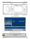
Figure 3-6. Analog In Connector
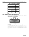
Pin assignments for the Analog In connector are presented in Table 3-3.
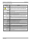
WARNING - ELECTRICAL SHOCK HAZARD
Never connect/disconnect PCAs, wiring harnesses or electronic subassemblies while
under power. Never operate with cover off.
07266B DCN6485