


Troubleshooting & Service Model T101 Instruction Manual
226
bubble solution, looking for fine bubbles. Once the fittings have been
wetted with soap solution, do not re-apply vacuum as it will draw soap
solution into the instrument and contaminate it. Do not exceed 15 psi
pressure.
4. If the instrument has the zero and span valve option, the normally closed
ports on each valve should also be separately checked. Connect the leak
checker to the normally closed ports and check with soap bubble
solution.
5. If the analyzer is equipped with an IZS Option, connect the leak checker
to the Dry Air inlet and check with soap bubble solution.
6. Once the leak has been located and repaired, the leak-down rate of the
indicated pressure should be less than 1 in-Hg-A (0.4 psi) in 5 minutes
after the pressure is turned off.
7. Clean soap solution from all surfaces, re-connect the sample and exhaust
lines, and replace the instrument cover. Restart the analyzer.
9.5.2. PERFORMING A SAMPLE FLOW CHECK
CAUTION
Use a separate, calibrated flow meter capable of measuring flows between 0 and 1000
cm³/min to measure the gas flow rate though the analyzer. Do not use the built in flow
measurement viewable from the front panel of the instrument.
Sample flow checks are useful for monitoring the actual flow of the instrument, to
monitor drift of the internal flow measurement. A decreasing, actual sample flow may
point to slowly clogging pneumatic paths, most likely critical flow orifices or sintered
filters. To perform a sample flow check:
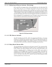
1. Disconnect the sample inlet tubing from the rear panel SAMPLE port
shown in Figure 3-2.
2. Attach the outlet port of a flow meter to the sample inlet port on the rear
panel. Ensure that the inlet to the flow meter is at atmospheric pressure.
3. The sample flow measured with the external flow meter should be 600
cm³/min 75 cm³/min. If a combined sample/ozone air Perma Pure dryer
is installed (optional equipment), the flow will be 740 cm³/min ± 10%
(600 cm³/min for the sample and 140 cm³/min for the ozone generator
supply air).
4. Low flows indicate blockage somewhere in the pneumatic pathway.
9.5.3. AC POWER CONFIGURATION
The T101 can be easily configured for two main power regimes, 100-120 V and 220-240
V at either 50 or 60 Hz. The analyzer is correctly configured for the AC power voltage
in use if it turns on and shows a front panel display after about 30 seconds. Internally,
several LEDs should turn on as soon as the power is supplied. If an incorrect power
configuration is suspected, check for the correct voltage and frequency at the line input
on the rear panel.
07266B DCN6485