


Operating Instructions Teledyne API – T101 Operation Manual
106
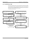
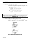
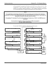
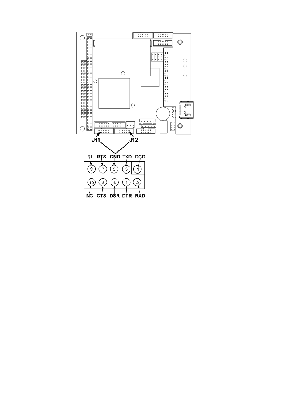
The signals from these two connectors are routed from the motherboard via a wiring
harness to two 10-pin connectors on the CPU card, J11 and J12.
Figure 4-8. CPU Connector Pin-Outs for RS-232 Mode
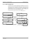
Teledyne API offers two mating cables, one of which should be applicable for your use.
Part number WR000077, a DB-9 female to DB-9 female cable, 6 feet long.
Allows connection of COM1 with the serial port of most personal
computers.
Part number WR000024, a DB-9 female to DB-25 male cable. Allows
connection to the most common styles of modems (e.g. Hayes-
compatible) and code activated switches.
Both cables are configured with straight-through wiring and should require no additional
adapters.
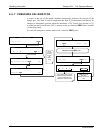
To assist in properly connecting the serial ports to either a computer or a modem, there
are activity indicators just above the COM1 port. Once a cable is connected between the
analyzer and a computer or modem, both the red and green LEDs should be on. If the
lights for COM 1 are not lit, use small switch on the rear panel to switch it between DTE
and DCE modes (see Section 4.7.5). If both LEDs are still not illuminated, check the
cable for proper wiring.
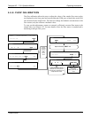
The two LEDs located o
v
er COM2 are currently deactivated. If you have problems
getting COM2 to activate, it may be necessary to install a null-modem cable (contact
Technical Support for information).
07266B DCN6485