


Model T101 Instruction Manual Troubleshooting & Service
225
Dirty sample chamber. Clean the sample chamber.
Insufficient time allowed for purging of lines upstream of the analyzer.
Insufficient time allowed for H
2
S calibration gas source to become stable.
9.4.3. THE ANALYZER DOESN’T APPEAR ON THE LAN OR
INTERNET
Most problems related to Internet communications via the Ethernet will be due to
problems external to the analyzer (e.g. bad network wiring or connections, failed routers,
malfunctioning servers, etc.). However, there are several symptoms that indicate the
problem may be with the Ethernet card itself.
If neither of the Ethernet cable’s two status LED’s (located on the back of the cable
connector) is lit while the instrument is connected to a network:
• Verify that the instrument is being connected to an active network jack.
• Check the internal cable connection between the Ethernet card and the
CPU board.
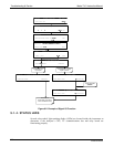
9.5. SUBSYSTEM CHECKOUT
The preceding sections of this manual discussed a variety of methods for identifying
possible sources of failures or performance problems within the analyzer. In most cases
this included a list of possible causes and, in some cases, quick solutions or at least a
pointer to the appropriate sections describing them. This section describes how to
determine if a certain component or subsystem is actually the cause of the problem being
investigated.
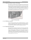
9.5.1. DETAILED PRESSURE LEAK CHECK
Obtain a leak checker similar to Teledyne API’s part number 01960, which contains a
small pump, shut-off valve, and pressure gauge to create both over-pressure and
vacuum. Alternatively, a tank of pressurized gas, with the two stage regulator adjusted to
≤ 15 psi, a shutoff valve and pressure gauge may be used.
CAUTION
Once tube fittings have been wetted with soap solution under a pressurized system, do not apply or re-
apply vacuum as this will cause soap solution to be sucked into the instrument, contaminating inside
surfaces.
Do not exceed 15 PSI when pressurizing the system.
1. Turn OFF power to the instrument and remove the instrument cover.
2. Install a leak checker or a tank of gas (compressed, oil-free air or
nitrogen) as described above on the sample inlet at the rear panel.
3. Pressurize the instrument with the leak checker or tank gas, allowing
enough time to fully pressurize the instrument through the critical flow
orifice. Check each tube connection (fittings, hose clamps) with soap
07266B DCN6485