Teledyne API T/E-Series Models 101, 102, and 108 Software Documentation (PN05492D DCN6485)
A-27
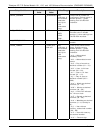
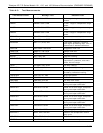
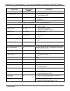
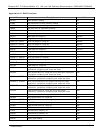
Signal Name
Bit or Channel
Number
Description
1 = all pressures OK
ST_TEMP_ALARM 4 0 = any temperature alarm
1 = all temperatures OK
ST_HVPS_ALARM 5 0 = HVPS alarm
1 = HVPS OK
6–7 Spare
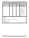
Front panel I
2
C keyboard, default I
2
C address 4E hex
MAINT_MODE 5 (input) 0 = maintenance mode
1 = normal mode
LANG2_SELECT 6 (input) 0 = select second language
1 = select first language (English)
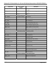
SAMPLE_LED 8 (output) 0 = sample LED on
1 = off
CAL_LED 9 (output) 0 = cal. LED on
1 = off
FAULT_LED 10 (output) 0 = fault LED on
1 = off
AUDIBLE_BEEPER 14 (output) 0 = beeper on (for diagnostic testing only)
1 = off
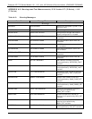
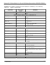
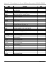
Relay board digital output (PCF8575), default I
2
C address 44 hex
RELAY_WATCHDOG 0 Alternate between 0 and 1 at least every 5 seconds
to keep relay board active
RCELL_HEATER 1 0 = reaction cell heater on
1 = off
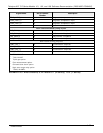
CONV_HEATER
1
2 0 = converter cell heater on
1 = off
3 Spare
IZS_HEATER 4 0 = IZS heater on
1 = off
5 Spare
CAL_VALVE 6 0 = let cal. gas in
1 = let sample gas in
SPAN_VALVE 7 0 = let span gas in
1 = let zero gas in
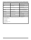
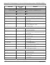
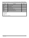
TRS_VALVE
3
8 0 = switch to TRS gas position
1 = primary gas position (SO2)
H2S_VALVE,
TRS_VALVE
0 = switch to secondary gas position (H2S/TRS)
1 = primary gas position (SO2)
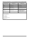
TS_VALVE
2
9
0 = primary gas position (SO2)
1 = switch to secondary gas position (TS)
2
07266B DCN6485


