


Model T101 Instruction Manual Principles Of Operation
269
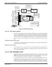
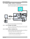
As a Safety measure, special circuitry on the Relay Board watches the status of LED D1.
Should this LED ever stay ON or OFF for 30 seconds, indicating that the CPU or I
2
C
bus has stopped functioning, the Watchdog Circuit will automatically shut of all valves
as well as turn off the UV Source(s) and all heaters. The Sample Pump will still be
running.
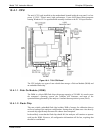
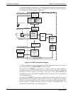
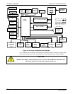
10.4.10. MOTHERBOARD
This printed circuit assembly provides a multitude of functions including A/D
conversion, digital input/output, PC-104 to I
2
C translation, temperature sensor signal
processing and is a pass through for the RS-232 and RS-485 signals.
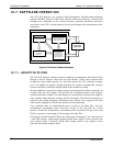
10.4.10.1. A to D Conversion
Analog signals, such as the voltages received from the analyzer’s various sensors, are
converted into digital signals that the CPU can understand and manipulate by the analog
to digital converter (A/D).Under the control of the CPU, this functional block selects a
particular signal input and then coverts the selected voltage into a digital word.
The A/D consists of a voltage-to-frequency (V-F) converter, a programmable logic
device (PLD), three multiplexers, several amplifiers and some other associated devices.
The V-F converter produces a frequency proportional to its input voltage. The PLD
counts the output of the V-F during a specified time period, and sends the result of that
count, in the form of a binary number, to the CPU.
The A/D can be configured for several different input modes and ranges but in the is
used in uni-polar mode with a +5V full scale. The converter includes a 1% over and
under-range. This allows signals from -0.05V to +5.05V to be fully converted.
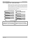
For A to D calibration purposes, two reference voltages are supplied to the A/D
converter: Reference ground and +4.096 VDC. During calibration the device measures
these two voltages and outputs their digital equivalent to the CPU. The CPU uses these
values to compute the A to D converter’s offset and slope (not the same offset and slope
recorded during zero/span calibration) and uses these factors for subsequent conversions.
See 4.6.3.4 for instructions on performing this calibration.
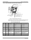
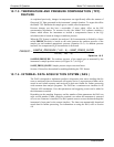
10.4.10.2. Sensor Inputs
The key analog sensor signals are coupled to the A/D through the master multiplexer
from two connectors on the motherboard. 100K terminating resistors on each of the
inputs prevent cross talk from appearing on the sensor signals.
PMT Detector Output: This signal, output by the PMT preamp PCA, is used in the
computation of the H
2
S concentration displayed at the top right hand corner of the front
panel display and output through the instrument’s analog outputs and COMM ports.
PMT HIGH VOLTAGE POWER SUPPLY LEVEL: This input is based on the drive
voltage output by the PMT pram board to the PMT’s high voltage power supply
(HVPS). It is digitized and sent to the CPU where it is used to calculate the voltage
setting of the HVPS and stored in the instrument’s memory as the test function HVPS.
HVPS is viewable as a test function (Section 4.2.1) through the analyzer’s front panel.
PMT TEMPERATURE:
This signal is the output of the thermistor attached to the PMT
cold block amplified by the PMT temperature feedback circuit on the PMT preamp
07266B DCN6485