


Model T101 Instruction Manual Troubleshooting & Service
237
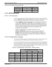
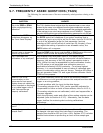
Table 9-9. Example of UV Lamp Power Supply Outputs
UVLAMP_SIGNAL ACTION TO BE TAKEN
3500mV±200mV. No Action Required
> 4900mV at any time.
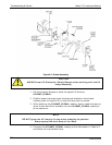
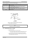
Adjust the UV reference detector potentiometer (refer to Figure 9-6)
until UVLAMP_SIGNAL reads approximately 3600mV before
continuing to adjust the lamp position.
>3700mV or < 3300mV
Adjust the UV reference detector potentiometer (refer to Figure 9-6)
until UVLAMP_SIGNAL reads as close to 3500mV as possible.
.< 600mV Replace the lamp.
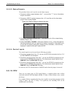
Figure 9-5. Location of UV Reference Detector Potentiometer
5. Finger tighten the thumbscrew.
NOTE
DO NOT over-tighten the thumbscrew.
9.6.3. REPLACING THE UV LAMP
1. Turn off the analyzer.
2. Disconnect the UV lamp from its power supply.
You can find the power supply connector by following the two, white
UV Lamp power supply wires from the lamp to the power supply.
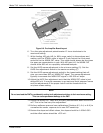
3. Loosen, but do not remove the two UV lamp bracket screws and the
large brass thumbscrew located on the shutter housing (refer to Figure
9-4) so tha
t the lamp can be moved.
07266B DCN6485