


Getting Started Teledyne API – T101 Operation Manual
50
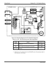
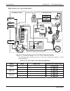
The state of the IZS valves can also be controlled:
Manually from the analyzer’s front panel by using the SIGNAL I/O
controls located under the DIAG Menu (Section 4.6.1),
By activati
ng the instrument’s AutoCal feature (Section 6.9),
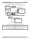
Remotely
by using the external digital control inputs (Section 5.1.1.2 and
Section 6.7.1), or
Remotely through the R
S-232/485 serial I/O ports (see Appendix A-6 for
the appropriate commands).
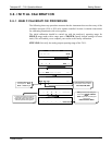
3.5. STARTUP, FUNCTIONAL CHECKS, AND INITIAL
CALIBRATION
If you are unfamiliar with the T101 theory of operation, we recommend that you read
Section 10 before proceeding.
For information on navi
gating the analyzer’s software menus, see the menu trees
described in Appendix A.1.
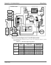
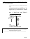
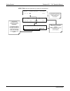
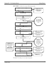
3.5.1. STARTUP
After the electrical and pneumatic connections are made, an initial functional check is in
order. Turn on the instrument. The pump and exhaust fan should start immediately. The
front panel display screen will briefly show a logo splash screen at the start of
initialization.
The analyzer should automatically switch to Sample Mode after completing the boot-up
sequence and start monitoring H
2
S gas. However, there is an approximately one hour
warm-up period before reliable gas measurements can be taken. During the warm-up
period, the front panel display may show messages in the Parameters field.
3.5.2. WARM-UP
Allow a 60-minute warm-up period before collecting sample data.
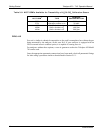
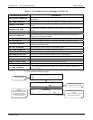
3.5.3. WARNING MESSAGES
Because internal temperatures and other conditions may be outside of specified limits
during the analyzer’s warm-up period, the software will suppress most warning
conditions for 60 minutes after power up.
If warning messages persist after 60 minutes, investigate their cause using the
troubleshooting guidelines in Section 9. The following table includes a brief description
of the various
warning m
essages that may appear.
07266B DCN6485