


Troubleshooting & Service Model T101 Instruction Manual
216
9.1.2. FAULT DIAGNOSIS WITH TEST FUNCTIONS
Besides being useful as predictive diagnostic tools, the TEST functions, viewable from
the front panel, can be used to isolate and identify many operational problems when
combined with a thorough understanding of the analyzer’s theory of operation (Section
10). We recommend use of the APICOM remote control program to download, graph
and archive TEST data for analys
is, and long-term monitoring of diagnostic data.
The acceptable ranges for these test functions are listed in Table A-3 in Appendix A-3.
The actual values for these test functions on checkout at the factory were also listed in
the Final Test and Validation Data Sheet, which was shipped with the instrument.
Values outside the acceptable ranges indicate a failure of one or more of the analyzer’s
subsystems. Functions with values that are within the acceptable range but have
significantly changed from the measurements recorded on the factory data sheet may
also indicate a failure or a maintenance item. A problem report worksheet has been
provided in Appendix C to assist in recording the value of these test functions. The
following table (Table 9-2) contains some of the more common causes for these values
to be out of range.
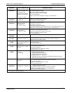
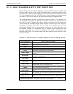
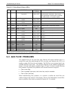
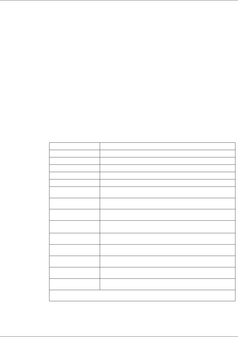
Table 9-2. Test Functions - Possible Causes for Out-Of-Range Values
TEST FUNCTION INDICATED FAILURE(S)
H2S STB
1
Unstable concentrations; leaks
SAMPLE FL
Leaks; clogged critical flow orifice
PMT
Calibration error; HVPS problem; PMT problem; No flow (leaks)
NORM PMT
Calibration error; HVPS problem; PMT problem
HVPS
HVPS broken; preamp board circuit problems
RCELL TEMP
Malfunctioning heater; relay board communication (I
2
C bus); relay
burnt out
BOX TEMP
Environment out of temperature operating range; broken
thermistor; runaway heater
PMT TEMP
TEC cooling circuit broken; High chassis temperature; 12V power
supply
IZS TEMP
(OPTION)
Malfunctioning heater; relay board communication (I
2
C bus); relay
burnt out
CONV TEMP
Malfunctioning heater or temperature sensor; relay board
communication (I
2
C bus); relay burnt out
PRESS
Leak; malfunctioning valve; malfunctioning pump; clogged flow
orifices; sample inlet overpressure;
H2S SLOPE
1
Calibration error; span gas concentration incorrect; leaks; low lamp
output
H2S OFFS
1
Incorrect span gas concentration/contaminated zero air/leak; low-
level calibration off
TIME OF DAY
Internal clock drifting; move across time zones; daylight savings
time?
1
Shown as they appear when analyzer is in H
2
S mode. In SO
2
mode appear as SO2 STB,
SO2 OFFS & SO2 SLOPE. In multigas mode, both versions appear.
07266B DCN6485