


Instrument Maintenance Model T101 Instruction Manual
210
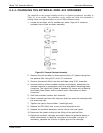
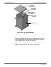
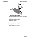
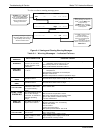
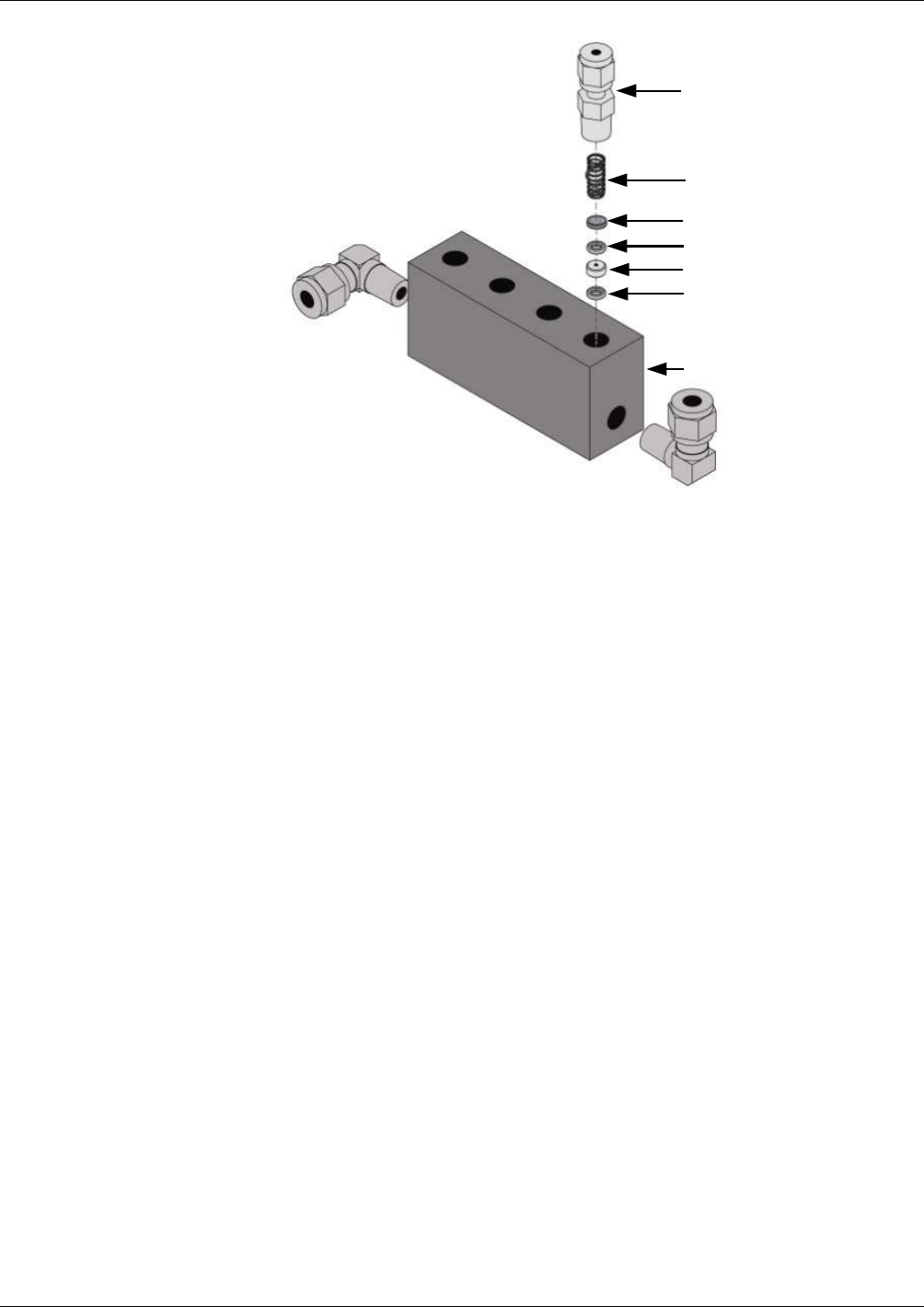
Gas Line fitting
Spring
Sintered Filter
O-Ring
Critical Flow Orifice
O-Ring
Vacuum Manifold
Figure 8-4. Critical Flow Orifice Assembly
5. Take out the components of the assembly: a spring, a sintered filter, two
O-rings and the critical flow orifice.
You may need to use a scribe or pressure from the vacuum port to get the parts out
of the manifold.
6. Discard the two O-rings and the sintered filter.
7. Replace the critical flow orifice.
8. Let the part dry.
9. Re-assemble the parts as shown in Figure 8-4 using a new filter and o-
rings.
10. Rein
st
all the NPT fitting and connect all tubing.
11. Power up the analyzer and allow it to warm up for 60 minutes.
8. Perform a leak check (refer to Section 9.5).
07266B DCN6485