


Getting Started Teledyne API – T101 Operation Manual
34
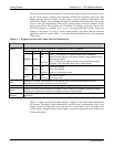
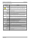
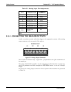
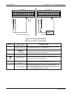
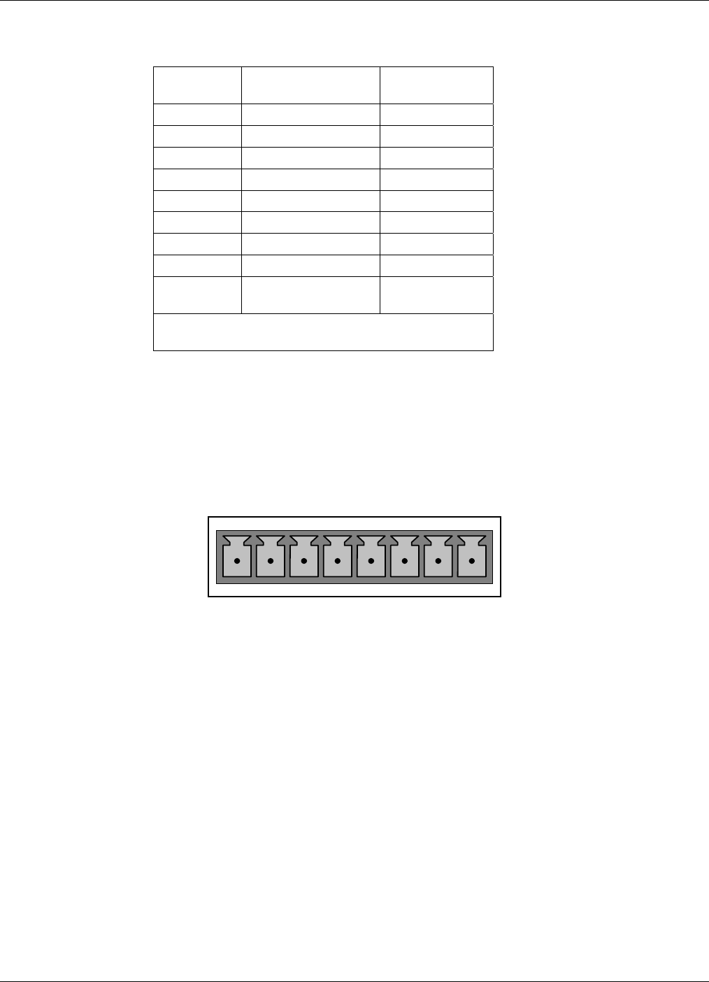
Table 3-3. Analog Input Pin Assignments
PIN DESCRIPTION
DAS
PARAMETER
1
1 Analog input # 1 AIN 1
2 Analog input # 2 AIN 2
3 Analog input # 3 AIN 3
4 Analog input # 4 AIN 4
5 Analog input # 5 AIN 5
6 Analog input # 6 AIN 6
7 Analog input # 7 AIN 7
8 Analog input # 8 AIN 8
GND
Analog input
Ground
N/A
1
See Section 4.8 for details on setting up the
DAS.
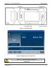
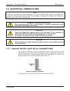
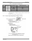
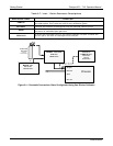
3.3.2. CONNECTING THE ANALOG OUTPUTS
Attach a strip chart recorder and/or data-logger to the appropriate contacts of the analog
output connecter on the rear panel of the analyzer.
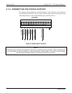
ANALOG OUT
A1 A2 A3 A4
+ - + - + - + -
Figure 3-7. Analog Output Connector
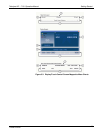
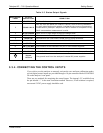
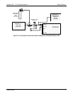
The A1 and A2 channels output a signal that is proportional to the H
2
S concentration of
the sample gas.
The output, labeled A4 is special. It can be set by the user (Section 4.6.9) to output any
one of the parame
ters accessible through the <TST TST> buttons of the unit’s Sample
display.
Pin-outs for the Analog Output connector at the rear panel of the instrument are presented
in Table 3-4.
07266B DCN6485