


Model T101 Instruction Manual Principles Of Operation
265
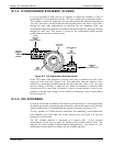
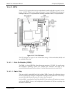
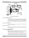
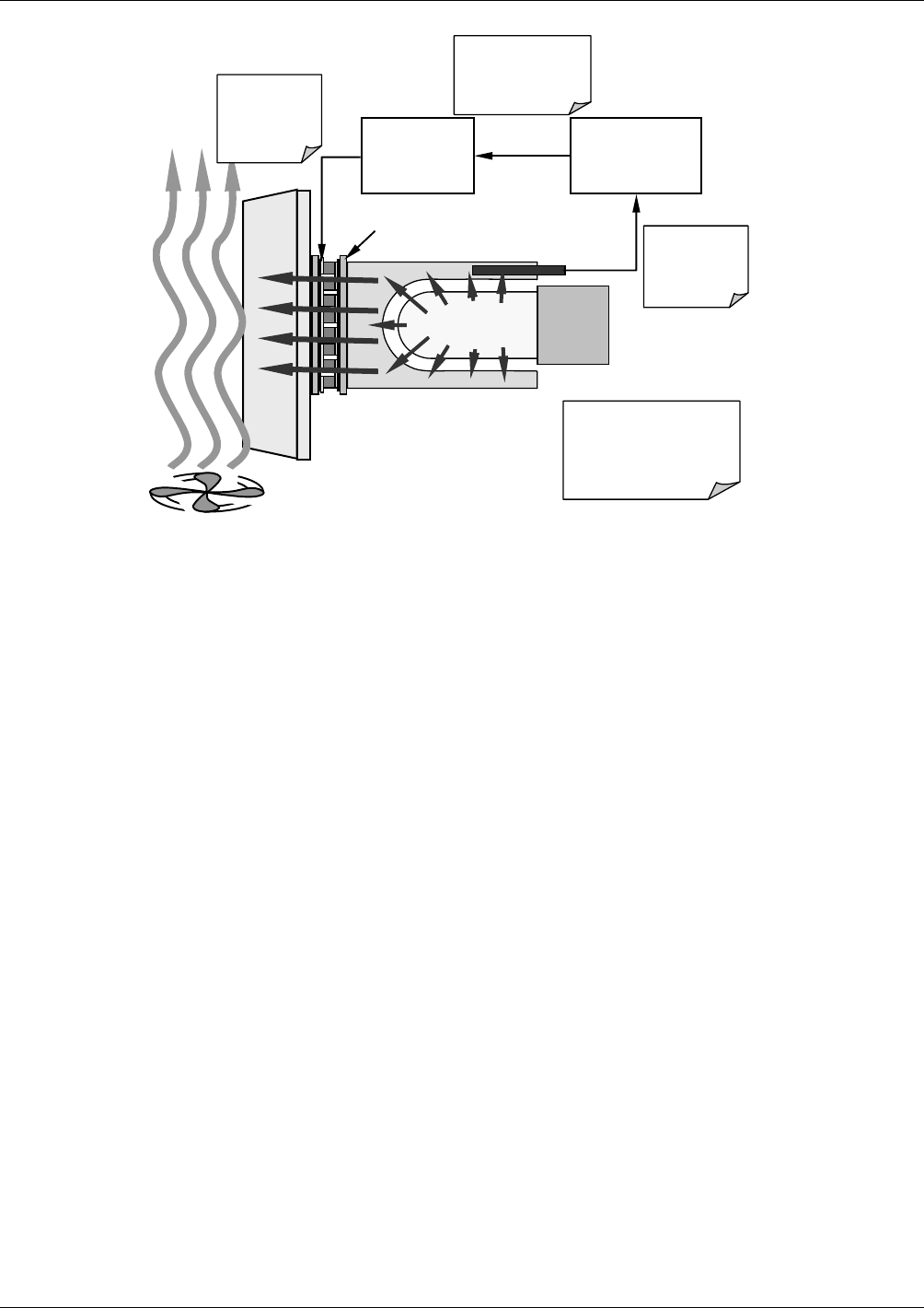
TEC
Control
PCA
PMT Preamp
PCA
Thermistor
outputs temp of
cold block to
preamp PCA
Preamp PCA sends
buffered and
amplified thermistor
signal to TEC PCA
TEC PCA sets
appropriate
drive voltage
for cooler
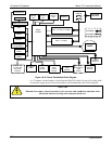
Heat from PMT is absorbed
by the cold block and
transferred to the heat sink
via the TEC then bled off
into the cool air stream.
PMT
Cold Block
Heat Sink
Cooling Fan
ThermoElectric Cooler
Figure 10-15. PMT Cooling System
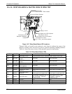
10.4.5.2. TEC Control Board
The TEC control printed circuit assembly is located on the sensor housing assembly,
under the slanted shroud, next to the cooling fins and directly above the cooling fan.
Using the amplified PMT temperature signal from the PMT preamplifier board (Section
10.4.6); it sets the drive voltage for the thermo
electric cooler. The warmer the PMT gets,
the more current is passed through the TEC causing it to pump more heat to the heat
sink.
TEC Control Power Status LED
A red LED located on the top edge of this assembly glows constantly to indicate that the
control circuit is receiving power.
TEC Control Test Points
Four test points are also located at the top of this assembly they are numbered left to
right start with the point immediately to the right of the power status LED. See Section
9.5.3 for more information.
10.4.6. PMT PREAMPLIFIER
The PMT preamplifier board amplifies the PMT signal into a useable analog voltage
(PMT) that can be processed by the motherboard into a digital signal to be used by the
CPU to calculate the H
2
S concentration of the gas in the sample chamber.
The output signal of the PMT is controlled by two different adjustments. First, the
voltage across the electron multiplier array of the PMT is adjusted with a set of two
hexadecimal switches. Adjusting this voltage directly affects the HVPS voltage and,
hence, the signal from the PMT. Secondly, the gain of the amplified signal can further
07266B DCN6485