


Principles Of Operation Model T101 Instruction Manual
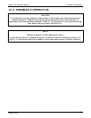
250
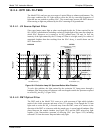
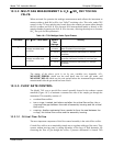
LAMP OUTPUT
(Arbitrary Untis)
10
5
10
4
10
2
10
3
10
1
1
100 200
300
400
500
WAVELENGTH (nm)
0
213.9
330.3
SO
2
* FLUORESCENT
SPECTRUM
PMT OPTICAL FILTER
BANDWIDTH
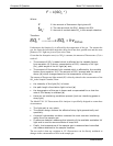
Figure 10-5. PMT Optical Filter Bandwidth
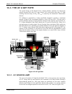
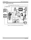
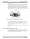
10.2.5. OPTICAL LENSES
Two optical lenses are used to focus and optimize the path of light through the sample
chamber.
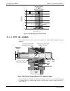
214 nm
Filter
330 nm
Filter
UV Source
Lens
PMT Lens
Reference
Detector
If source UV is unfocused, PMT
receives fluorescence from area
outside Reference Detector’s view
PMT
When source UV is focused, PMT
and Reference Detector view
similar volume of SO
2
*
When source UV is focused,
Reference Detector sees
most of the emitted light
If source UV is unfocused,
Reference Detector only sees a
small portion of emitted light
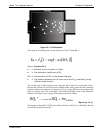
Figure 10-6. Effects of Focusing Source UV in Sample Chamber
A lens located between PMT and the sample chamber collects as much of the fluoresced
UV created there as possible and focuses it on the most sensitive part of the PMT’s
photo cathode.
07266B DCN6485