Teledyne API – T101 Operation Manual Operating Instructions
93
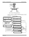
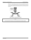
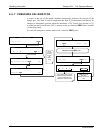
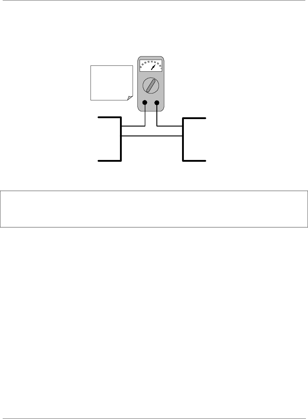
Similar to the voltage calibration, the software allows this current adjustment to be made
in 100, 10 or 1 count increments. Since the exact current increment per voltage count
varies from output to output and from instrument to instrument, you will need to measure
the change in the current with a current meter placed in series with the output circuit
(Figure 4-5).
mA
IN OU
T
I OUT +
I OUT -
I IN +
I IN -
Recording
Device
Analyzer
See Table 3-2 for
pin assignments of
the Analog Out
connector on the
rear panel.
Figure 4-5. Setup for Calibrating Current Outputs
NOTE
Do not exceed 60 V between current loop outputs and instrument ground.
07266B DCN6485


