


Principles Of Operation Model T101 Instruction Manual
260
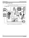
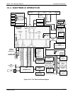
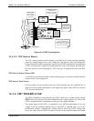
The core of the analyzer is a microcomputer that controls various internal processes,
interprets data, makes calculations, and reports results using specialized firmware
developed by Teledyne API. It communicates with the user as well as receives data from
and issues commands to a variety of peripheral devices through a separate printed circuit
assembly to which the CPU is mounted: the motherboard.
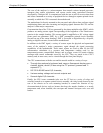
The motherboard is directly mounted to the rear panel and collects data, performs signal
conditioning duties and routs incoming and outgoing signals between the CPU and the
analyzer’s other major components.
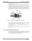
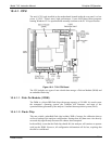
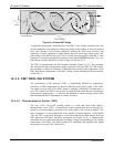
Concentration data of the T101 are generated by the photo multiplier tube (PMT), which
produces an analog current signal corresponding to the brightness of the fluorescence
reaction in the sample chamber. This current signal is amplified to a DC voltage signal
(front panel test parameter PMT) by a PMT preamplifier printed circuit assembly
(located on top of the sensor housing). PMT is converted to digital data by a bi-polar,
analog-to-digital converter, located on the motherboard.
In addition to the PMT signal, a variety of sensors report the physical and operational
status of the analyzer’s major components, again through the signal processing
capabilities of the motherboard. These status reports are used as data for the H
2
S
concentration calculation (e.g. pressure and temperature reading used by the
temperature/pressure compensation feature) and as trigger events for certain warning
messages and control commands issued by the CPU. They are stored in the CPU’s
memory and, in most cases, can be viewed through the front panel display.
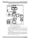
The CPU communicates with the user and the outside world in a variety of ways:
Through the analyzer’s keyboard and vacuum fluorescent display over a
clocked, digital, serial I/O bus using the I
2
C protocol (pronounced “I-
squared-C”);
RS 232 & RS485 serial I/O channels;
Various analog voltage and current outputs and
Several digital I/O channels.
Finally, the CPU issues commands (also over the I
2
C bus) to a series of relays and
switches located on a separate printed circuit assembly, the relay board (located in the
rear of the chassis on its own mounting bracket) to control the function of key
electromechanical devices such as heaters that keep the sample chamber at a steady
temperature and, when installed, the zero/span and internal zero/span valve sets and
heaters.
07266B DCN6485