


Operating Instructions Teledyne API – T101 Operation Manual
58
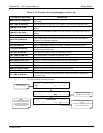
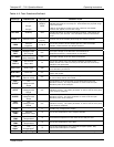
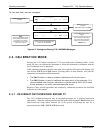
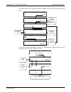
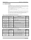
MODE DESCRIPTION
SETUP X.#
2
SETUP mode is being used to configure the analyzer. The gas measurement will
continue during this process.
SPAN CAL A
1
Unit is performing SPAN calibration initiated automatically by the analyzer’s
AUTOCAL feature
SPAN CAL M
1
Unit is performing SPAN calibration initiated manually by the user.
SPAN CAL R
1
Unit is performing SPAN calibration initiated remotely through the COM ports or
digital control inputs.
ZERO CAL A
1
Unit is performing ZERO calibration procedure initiated automatically by the
AUTOCAL feature
ZERO CAL M
1
Unit is performing ZERO calibration procedure initiated manually by the user.
ZERO CAL R
1
Unit is performing ZERO calibration procedure initiated remotely through the COM
ports or digital control inputs.
1
Only Appears on units with Z/S valve or IZS options
2
The revision of the analyzer firmware is displayed following the word SETUP, e.g., SETUP c.4
Finally, the various CAL modes allow calibration of the analyzer. Calibration is described
in Section 6.
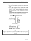
4.2. SAMPLE MODE
This is the analyzer’s standard operating mode. In this mode, the instrument is analyzing
H
2
S
and
calculating concentrations.
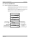
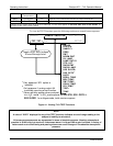
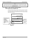
4.2.1. TEST FUNCTIONS
A series of test functions is available at the front panel while the analyzer is in SAMPLE
mode. These parameters provide information about the present operating status of the
instrument and are useful during troubleshooting (Section 9.1.2). They can also be
recorded in one of the DAS channels (Section 4.8) for data ana
lysis. To view the test
functions, press one of the <TST TST
> buttons repeatedly in either direction.
07266B DCN6485