Model T101 Instruction Manual Troubleshooting & Service
239
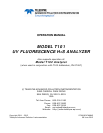
Figure 9-6. Pre-Amplifier Board Layout
6. Turn the gain adjustment potentiometer 12 turns clockwise to its
maximum setting.
7. While feeding 400 ppb H
2
S (or 80% range value) to the analyzer and
waiting until the STABIL value is below 0.5 ppb look at the front panel
and scroll to the NORM PMT value. This value should always be two times
the span gas concentration in ppb. With 400 ppb H
2
S, the NORM PMT
should show 800 mV on a properly calibrated analyzer.
8. Set the HVPS coarse adjustment to its minimum setting (0). Set the
HVPS fine adjustment switch to its maximum setting (F).
9. Set the HVPS coarse adjustment switch to the lowest setting that will
give you more than 800 mV NORM PMT signal. The coarse adjustment
typically increments the NORM PMT signal in 100-300 mV steps.
10. Adjust the HVPS fine adjustment such that the NORM PMT value is just
above 800 mV. It may be necessary to go back and forth between coarse
and fine adjustments if the proper value is at the threshold of the
min/max coarse setting.
NOTE
Do not overload the PMT by accidentally setting both adjustment switches to their maximum setting.
This can cause permanent damage to the PMT.
11. Adjust the NORM PMT value with the gain potentiometer down to 800±10
mV. This is the final very-fine adjustment.
12. Perform software span and zero calibrations (Sections 6.2, 6.4, or 6.8) to
normalize th
e sensor response to its new PMT sensitivity.
13. Review the slope and offset values, the slopes should be 1.000±0.300
and the offset values should be <250 mV.