


Troubleshooting & Service Model T101 Instruction Manual
234
The IZS option is heated with a proportional heater circuit and the temperature is
maintained at 50° C ±1°. Check the IZS TEMP function via front panel display (Section
4.2.1) and the IZS_TEM
P signal voltage using the SIGNAL I/O function under the
DIAG Menu (Section 4.6.1). At 50°
C, the temperature signal from the IZS thermistor
should be around 2500 mV.
9.5.18. BOX TEMPERATURE
The box temperature sensor (thermistor) is mounted on the motherboard at the bottom,
right corner of the CPU board when looking at it from the front. It cannot be
disconnected to check its resistance. Box temperature will vary with, but will always
read about 5° C higher than, ambient (room) temperature because of the internal heating
zones from the H
2
S converter, sample chamber and other devices. To check the box
temperature functionality, we recommend checking the BOX_TEMP signal voltage
using the SIGNAL I/O function under the DIAG Menu (Section 4.6.1). At about 30°
C
(5 above typical room temperature), the signal should be around 1500 mV. We
recommend using a certified or calibrated external thermometer / temperature sensor to
verify the accuracy of the box temperature.
9.5.19. PMT TEMPERATURE
PMT temperature should be low and constant. It is more important that this temperature
is maintained constant than it is to maintain it low. The PMT cooler uses a Peltier,
thermo-electric element powered by 12 VDC from the switching power supply PS2. The
temperature is controlled by a proportional temperature controller located on the
preamplifier board. Voltages applied to the cooler element vary from +/- 0.1 to +/- 12
VDC. The temperature set point (hard-wired into the preamplifier board) will vary by
about ±1 C due to component tolerances. The actual temperature will be maintained to
within 0.1 C around that set point. On power-up of the analyzer, the front panel enables
the user to watch that temperature drop from about ambient temperature down to its set
point of 6-8° C. If the temperature fails to drop after 20 minutes, there is a problem in
the cooler circuit. If the control circuit on the preamplifier board is faulty, a temperature
of -1 C is reported.
9.6. REPAIR PROCEDURES
This section contains some procedures that may need to be performed when a major
component of the analyzer requires repair or replacement. Note that replacement
procedures that are discussed in detail in Section 8 (Maintenance) are not listed here.
Servicing of circuit components requ
ires electrostatic discharge protection, i.e. ESD
grounding straps, mats and containers. Failure to use ESD protection when working
with electronic assemblies will void the instrument warranty.
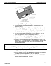
9.6.1. DISK-ON-MODULE REPLACEMENT
Replacing the Disk-on-Module (DOM) will cause loss of all DAS data; it also may
cause loss of some instrument configuration parameters unless the replacement DOM
carries the exact same firmware version. Whenever changing the version of installed
software, the memory must be reset. Failure to ensure that memory is reset can cause the
analyzer to malfunction, and invalidate measurements. After the memory is reset, the
A/D converter must be re-calibrated, and all information collected in Step 1 below must
07266B DCN6485