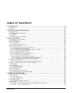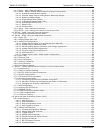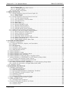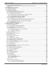
Teledyne API – T101 Operation Manual TABLE OF CONTENTS
xvii
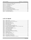
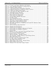
Table 4-14. Current Loop Output Calibration with Resistor ..................................................... 94
Table 4-15. Test Parameters Available for Analog Output A4 ................................................ 102
Table 4-16. Ethernet Status Indicators .............................................................................. 107
Table 4-17. LAN/Internet Default Configuration Properties ................................................... 109
Table 4-18. Internet Configuration Touchscreen Button Functions ......................................... 113
Table 4-19. COMM Port Communication Modes ................................................................... 121
Table 4-20. Front Panel LED Status Indicators for DAS ........................................................ 125
Table 4-21. DAS Data Channel Properties .......................................................................... 126
Table 4-22. DAS Data Parameter Functions........................................................................ 127
Table 5-1. Status Output Pin Assignments ......................................................................... 145
Table 5-2. Control Input Pin Assignments .......................................................................... 145
Table 5-3. Terminal Mode Software Commands .................................................................. 147
Table 5-4. Command Types ............................................................................................. 148
Table 5-5. Serial Interface Documents .............................................................................. 154
Table 5-6. Hessen RS-232 Communication Parameters ........................................................ 155
Table 5-7. T101 Hessen Protocol Response Modes............................................................... 157
Table 5-8. Default Hessen Status Bit Assignments .............................................................. 160
Table 6-1. NIST-SRM's Available for Traceability of H2S and SO2 Calibration Gases ................. 165
Table 6-2. AutoCal Modes................................................................................................ 179
Table 6-3. AutoCal Attribute Setup Parameters................................................................... 180
Table 6-4. Example Auto-Cal Sequence ............................................................................. 181
Table 6-5. Example Auto-Cal Sequence ............................................................................. 185
Table 7-1. Activity Matrix for Calibration Equipment & Supplies............................................. 188
Table 7-2. Activity Matrix for Calibration Procedure ............................................................. 189
Table 7-3. Activity Matrix ................................................................................................ 191
Table 7-4. Definition of Level 1 and Level 2 Zero and Span Checks........................................ 192
Table 8-1 T101 Preventive Maintenance Schedule ............................................................... 199
Table 8-2 Predictive Uses for Test Functions....................................................................... 201
Table 9-1. Warning Messages - Indicated Failures............................................................... 214
Table 9-2. Test Functions - Possible Causes for Out-Of-Range Values .................................... 216
Table 9-3. Relay Board Status LEDs .................................................................................. 220
Table 9-4. DC Power Test Point and Wiring Color Code ........................................................ 227
Table 9-5. DC Power Supply Acceptable Levels ................................................................... 227
Table 9-6. Relay Board Control Devices ............................................................................. 229
Table 9-7. Analog Output Test Function - Nominal Values .................................................... 229
Table 9-8. Status Outputs Check Pin Out ........................................................................... 230
Table 9-9. Example of UV Lamp Power Supply Outputs........................................................ 237
07266B DCN6485


