


Troubleshooting & Service Model T101 Instruction Manual
238
NOTE
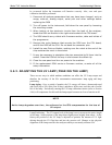
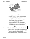
DO NOT grasp the UV lamp by its cap when changing its position (refer to Figure 9-4).
Always grasp the main body of the lamp.
4. Remove the UV Lamp by pulling it straight up.
5. Insert the new UV lamp into the bracket.
6. Tighten the two UV lamp bracket screws, but leave the brass thumb
screw un-tightened.
7. Connect the new UV lamp to the power supply.
8. Turn the instrument on and perform the UV adjustment procedure as
defined in Section 9.6.2. above.
9. Fin
g
er tighten the thumbscrew.
NOTE
DO NOT over-tighten the thumbscrew.
10. Perform a lamp calibration procedure (refer to Section 4.6.6) and a zero
point and span point calibration (refer to Section 6).
9.6.4. FACTORY CAL (PMT SENSOR, HARDWARE CALIBRATION)
The sensor module hardware calibration adjusts the slope of the PMT output when the
Instrument’s slope and offset values are outside of the acceptable range and all other
more obvious causes for this problem have been eliminated.
1. Set the instrument reporting range to SNGL (Section 4.4.4.4)
2. Perform a full zero calibration using zero air (Sections 6.2, 6.4, or 6.8).
3. Let
the instrument run for one hour to stabilize the lamp and run a lamp
calibration from the diagnostic menu. This is required to ensure proper
scaling of the NORM PMT value.
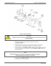
4. Locate the Preamp board (Figure 3-9).
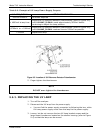
5. Locate the following components on the Preamp board (Figure 9-7):
HVPS coarse adjustment switch (Range 0-9, then A-F)
HVPS fine adjustment switch (Range 0-9, then A-F)
Gain adjustment potentiometer (Full scale is 10 turns).
07266B DCN6485