


Troubleshooting & Service Model T101 Instruction Manual
220
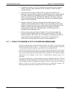
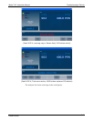
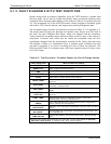
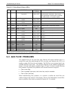
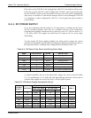
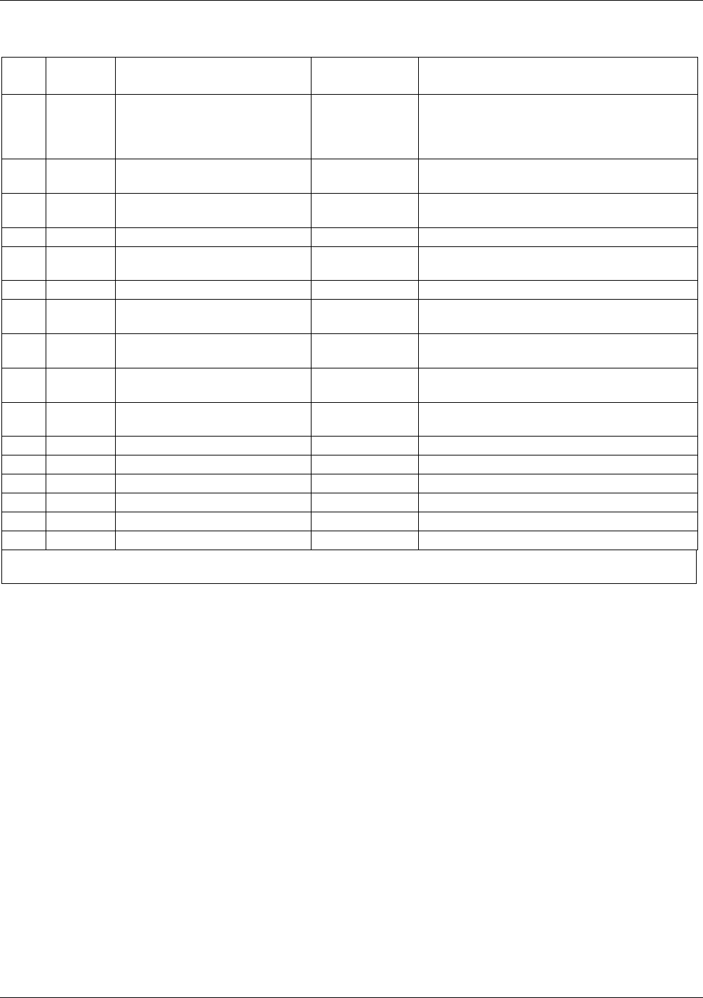
Table 9-3. Relay Board Status LEDs
LED COLOR FUNCTION FAULT
STATUS
INDICATED FAILURE(S)
D1 red Watchdog Circuit; I2C bus
operation.
Continuously
ON or OFF
Failed or halted CPU; faulty
motherboard, keyboard, relay board;
wiring between motherboard, keyboard
or relay board; +5 V power supply.
D2 yellow Relay 0 - sample chamber
heater
Continuously
ON or OFF
Heater broken, thermistor broken
D3 yellow Relay 1 – H
2
S converter
heater
Continuously
ON or OFF
Heater broken, thermocouple broken
D4
1
yellow Spare N/A N/A
D5 yellow Relay 3 - IZS heater Continuously
ON or OFF
Heater broken, thermistor broken
D6 yellow Relay 4 - Spare N/A N/A
D7
2
green Valve 0 - zero/span valve
status
Continuously
ON or OFF
Valve broken or stuck, valve driver chip
broken
D8
2
green Valve 1 - sample/cal valve
status
Continuously
ON or OFF
Valve broken or stuck, valve driver chip
broken
D9 green Valve 2 - auto-zero valve
status
Continuously
ON or OFF
Valve broken or stuck, valve driver chip
broken
D10 green Valve 3 - SO/SOx valve
status
Continuously
ON or OFF
Valve broken or stuck, valve driver chip
broken
D11 green Valve 4 - Spare N/A N/A
D12 green Valve 5 - Spare N/A N/A
D13 green Valve 6 - Spare N/A N/A
D14 green Valve 7 - Spare N/A N/A
D15 green Mosfet1-Unused N/A N/A
D16 Green Mosfet2-Unused N/A N/A
1
Special configurations only
2
Only active for instruments with Z/S valve or IZS options installed
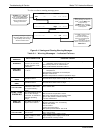
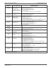
9.2. GAS FLOW PROBLEMS
The standard T101 has one main flow path. With the IZS option installed, there is a
second flow path flow path through the IZS oven that runs whenever the IZS is on
standby to purge H
2
S from the oven chamber. The IZS flow is not measured and is not
available from the front panel. The full flow diagrams of the standard configuration
(Figure 3-10) and with options installed (Figure 3-2 and 5-3) help in trouble-shooting
flow problems. In general, flow problems can be divided into three categories:
Flow is too high
Flow is greater than zero, but is too low, and/or unstable
Flow is zero (no flow)
When troubleshooting flow problems, it is essential to confirm the actual flow rate
without relying on the analyzer’s flow display. The use of an independent, external flow
meter to perform a flow check as described in Section 9.5.2 is essential.
07266B DCN6485