


Model T101 Instruction Manual Troubleshooting & Service
231
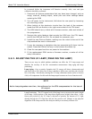
In some rare circumstances, this failure may be caused by a bad IC on the motherboard,
specifically U57, the large, 44 pin device on the lower right hand side of the board. If
this is true, removing U57 from its socket will allow the instrument to start up but the
measurements will be invalid.
If the analyzer stops during initialization (the front panel display shows a fault or
warning message), it is likely that the DOM, the firmware or the configuration and data
files have been corrupted.
9.5.11. RS-232 COMMUNICATION
9.5.11.1. General RS-232 Troubleshooting
Teledyne API analyzers use the RS-232 protocol as the standard, serial communications
protocol. RS-232 is a versatile standard, which has been used for many years but, at
times, is difficult to configure. Teledyne API instruments conform to the standard pin
assignments in the implementation of RS-232. Problems with RS-232 connections
usually center around 4 general areas:
Incorrect cabling and connectors. This is the most common problem. See
Figure 4-8 for connector and pin-out information and Section 4.7.3.
The communications (baud) rate
and protocol parameters are incorrectly
configured. See Section 4.7.11 on how to set the baud rate.
The COM port communi
cations mode is set incorrectly (Section 4.7.10).
If a modem is used, additional confi
guration and wiring rules must be
observed. See Section 5.1.2.7.
Incorrect setting of the
DTE - DCE Switch is set correctly See Section
4.7.5.
9.5.11.2. Modem or Terminal Operation
These are the general steps for troubleshooting problems with a modem connected to a
Teledyne API analyzer.
Check cables for proper connection to the modem, terminal or computer.
Check the correct position of the DTE/DCE as described in Section 4.7.5.
Check the co
rrect setup command (Section 5.1.2.7).
Verify that the Ready to
Send (RTS) signal is at logic high. The T101 sets
pin 7 (RTS) to greater than 3 volts to enable modem transmission.
Make sure the baud rate, word length, and stop bit settings between
modem and analyzer match, see Section 5.1.2.7 and Section 4.7.
Use the RS-232 test function to se
nd “w” characters to the modem,
terminal or computer; See Section 4.7.10.
Get your terminal, mod
em or computer to transmit data to the analyzer
(holding down the space bar is one way). The green LED on the rear
panel should flicker as the instrument is receiving data.
Make sure that the communications software is functioning properly.
07266B DCN6485