


Principles Of Operation Model T101 Instruction Manual
270
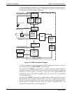
board. It is digitized and sent to the CPU where it is used to calculate the current
temperature of the PMT.
This measurement is stored in the analyzer’s memory as the test function PMT TEMP
and is viewable as a test function (Section 4.2.1) through the analyzer’s front panel.
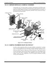
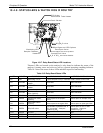
SAMPLE GAS PRESSURE SENSOR
: This sensor measures the gas pressure
at the exit
of the sample chamber.
SAMPLE FLOW SENSOR: This sensor measure the flow rate of the sample gas as it
exits the sample chamber.
10.4.10.3. Thermistor Interface
This circuit provides excitation, termination and signal selection for several negative-
coefficient, thermistor temperature sensors located inside the analyzer. They are:
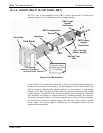
SAMPLE CHAMBER TEMPERATURE SENSOR: The source of this signal is a
thermistor embedded in the of the sample chamber block. It measures the temperature of
the sample gas in the chamber. This data are used by the CPU to control sample chamber
the heating circuit and as part of the H
2
S, calculations when the instrument’s
Temperature/Pressure Compensation feature is enabled.
This measurement is stored in the analyzer memory as a parameter (RCEL TEMP) and
is viewable as a test function under the same name (Section6.2.1) through the analyzer’s
front panel.
IZS OPTION PERMEATION TUBE TEMPERATURE SENSOR: This thermistor,
attached to the permeation tube in the IZS option, reports the current temperature of that
tube to the CPU as part of control loop that keeps the tube at a constant temperature.
BOX TEMPERATURE SENSOR: A thermistor is attached to the motherboard. It
measures the analyzer’s inside temperature. This information is stored by the CPU and
can be viewed by the user for troubleshooting purposes through the front panel display.
This measurement is stored in the analyzer. Memory as the test function BOX TEMP
and is viewable as a test function (Section 4.2.1) through the analyzer’s front panel.
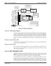
10.4.11. ANALOG OUTPUTS
The analyzer comes equipped with four Analog Outputs: A1, A2, A4 and a fourth that is
a spare.
A1 and A2 Outputs: The first two, A1 and A2 are normally set up to operate in parallel
so that the same data can be sent to two different recording devices. While the names
imply that one should be used for sending data to a chart recorder and the other for
interfacing with a data logger, either can be used for both applications.
Both of these channels output a signal that is proportional to the H
2
S concentration of
the sample gas. The A1 and A2 outputs can be slaved together or set up to operated
independently. A variety of scaling factors are available; see Section 4.4.4 for
information
on setting the reporting range type and scaling factors for these output
channels
Test Output: The third analog output, labeled A4 is special. It can be set by the user (see
Section 4.6.9) to carry the current signal level of any one of the parameters accessible
throug
h the TE
ST menu of the unit’s software.
07266B DCN6485