


Operating Instructions Teledyne API – T101 Operation Manual
64
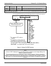
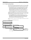
4.4. SETUP MODE
The SETUP mode allows you to configure the analyzer’s hardware and software features,
perform diagnostic procedures, gather information on the instrument’s performance and
configure or access data from the internal data acquisition system (DAS). For a visual
representation of the software menu trees, refer to Appendix A.
Pressing the SETUP button activates a prompt for a security password. The default
password is 818. Press ENTR to proceed.
However, there is the option to enable a higher level of security; described in Section
4.4.5.
Other passwo
rd levels exist allowing ac
cess to special diagnostic tools and variables used
only for specific and rarely needed troubleshooting and adjustment procedures. They
may be made available as needed by Teledyne API’s Technical Support department.
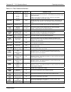
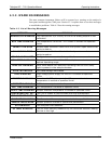
The following two tables decribe the menus under Setup mode:
Table 4-4. Primary Setup Mode Features and Functions
MODE OR FEATURE
TOUCHSCREEN
BUTTON
DESCRIPTION
MANUAL
SECTION
Analyzer Configuration CFG
Lists key hardware and software configuration
information
4.4.1
Auto Cal Feature ACAL
Used to set up and operate the AutoCal feature.
Only appears if the analyzer has one of the internal
valve options installed
6.9
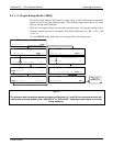
Internal Data Acquisition
system (DAS )
DAS
Used to set up the DAS system and view recorded
data
4.8
Analog Output Reporting
Range Configuration
RNGE
Used to configure the output signals generated by
the instrument’s Analog outputs.
4.4.4
Calibration Password
Security
PASS Turns the calibration password feature ON/OFF 4.4.5
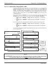
Internal Clock
Configuration
CLK
Used to Set or adjust the instrument’s internal
clock
4.4.6
Advanced SETUP
features
MORE
This button accesses the instrument’s secondary
setup menu
(Table
4-5)
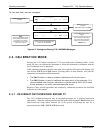
Table 4-5. Secondary Setup Mode Features and Functions
MODE OR FEATURE
TOUCHSCREEN
BUTTON
DESCRIPTION
MANUAL
SECTION
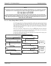
External Communication
Channel Configuration
COMM
Used to set up and operate the analyzer’s various
external I/O channels including RS-232; RS 485,
modem communication and/or Ethernet access.
4.7 & 5
System Status Variables VARS
Used to view various variables related to the
instrument’s current operational status
4.5
System Diagnostic
Features
DIAG
Used to access a variety of functions that are used
to configure, test or diagnose problems with a
variety of the analyzer’s basic systems
4.6
07266B DCN6485