


Model T101 Instruction Manual Principles Of Operation
267
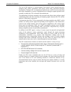
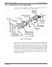
10.4.7. PNEUMATIC SENSOR BOARD
The flow and pressure sensors of the T101 are located on a printed circuit assembly just
behind the PMT sensor. Refer to Section 9.5.15 on how to test this assembly. The
signals of this board are supplied to the mo
therboard for further signal processing. All
sensors are linearized in the firmware and can be span calibrated from the front panel.
See Section 4.6.7 for instructions on performing this test.
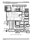
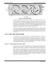
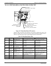
10.4.8. RELAY BOARD
The relay board is the central switching unit of the analyzer. It contains power relays,
status LEDs for all heated zones and valves as well as valve drivers, thermocouple
amplifiers, power distribution connectors and the two switching power supplies of the
analyzer. The relay board communicates with the motherboard over the I
2
C bus and is
the main board for trouble-shooting power problems of any kind.
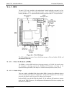
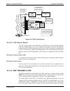
10.4.8.1. Heater Control
The T101 uses a variety of heaters for its individual components. All heaters are AC
powered and can be configured for 100/120 VAC or 220/230VAC at 50-60 Hz.
The two sample chamber heaters are electronically connected in parallel for analyzers at
100/120 VAC line power and in series for units configured for 220/230 VAC. One
configuration plug on the relay board determines the power configuration for the entire
analyzer.
On units with IZS options installed, an additional set of AC heaters is attached to the IZS
permeation tube. Some special T101 models may have other, non-standard heating zones
installed, such as a dilution manifold.
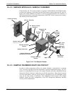
In order to operate efficiently, the H
2
S SO
2
converter must be heated to 315˚C. An
AC band heater wrapped around the converter cartridge contains two heater coils that
are also configured in parallel or in series depending on the Type of AC power being
supplied. A thermocouple imbedded in the heater measures the temperature and feeds a
small voltage to the relay board’s thermocouple amplifier, which, in turn, transmits the
linearized analog voltage to the motherboard. This information is sent to the CPU via
the instrument’s I2C buss. The CPU returns activate/deactivate signals to the
appropriate relay also via the I2C buss.
On units with IZS options installed, an additional set of AC heaters is attached to the IZS
oven. Some special T101 models may have other, non-standard heating zones installed,
such as a bypass manifold.
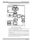
10.4.8.2. Valve Control
The relay board also hosts two valve driver chips, each of which can drive up four
valves. In its basic configuration the Model T101 requires no special valves to operate.
However, on units with either the zero/span valve or the IZS option installed The valves
are. Manifold valves may also be present in certain special versions of the analyzer.
07266B DCN6485