


Teledyne API – T101 Operation Manual Calibration Procedures
163
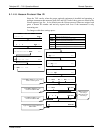
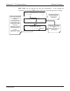
6. CALIBRATION PROCEDURES
This Section describes the calibration procedures for the T101. All of the methods
described in this section can be initiated and controlled through the COM ports.
NOTE
If you are using the T101 for US-EPA controlled monitoring of SO
2
, see Section 8 for
information on the EPA calibration protocol.
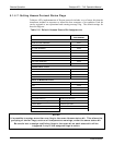
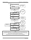
6.1. CALIBRATION PREPARATIONS
The calibration procedures in this section assume that the analog output reporting range
and units of measure, reporting range mode, and reporting range span have already been
selected for the analyzer. If this has not been done, please do so before continuing
(Section 4.4.4 for instructions).
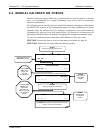
Also, unless otherwise s
tated, the procedures in this Section are written with the
assumption that the T101 is being used in its default configuration as an H
2
S analyzer.
The same methods and setups can be followed when the instrument is configured for SO
2
measurement by substituting SO
2
span gas for the H2S span gas listed in the procedure.
For analyzers configured in H
2
S SO
2
multigas mode, see Section 6.8
NOTE
In applications where the instrument may be used to measure SO
2
as well as H
2
S make
sure that the calibration gas being used matches the gas measurement mode in which
the instrument is set during the calibration procedure.
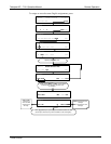
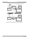
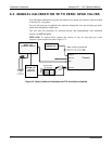
6.1.1. REQUIRED EQUIPMENT, SUPPLIES, AND EXPENDABLES
Calibration of the Model T101 analyzer requires a certain amount of equipment and
supplies. These include, but are not limited to, the following:
Zero-air source
Hydrogen sulfide span gas source
Gas lines - all gas line materials should be Teflon-type or glass.
A recording device such as a strip-chart recorder and/or data logger
(optional).
07266B DCN6485