


Principles Of Operation Model T101 Instruction Manual
272
AC POWER
ENTRANCE
ON/OFF
SWITCH
PS 1 (+5 VDC; ±15 VDC)
PS 2 (+12 VDC)
Chassis
Cooling
Fan
IZS Option
Permeation
Tube
Heater
PUMP
Sample
Chamber
Heaters
Sample/Cal
for Z/S and
IZS Valve
Options
AC POWER
DC POWER
UV Source
Lamp
Power
Su
pp
l
y
PMT
Cooling
Fan
PMT
Preamp
UV Source
Lamp
Shutter
TEC
Control
PCA
UV Source
Lamp
Shutter
H
2
S SO
2
Converter
Heaters
H
2
S SO
2
Vlavle
RELAY
BOARD
Pressure
Sensor
Mother
Board
CPU
PMT High
Voltage Supply
Temperature
Sensors
Gas Flow
Sensor
USB
LVDS transmitter board
Display
Touchscreen
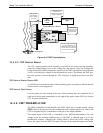
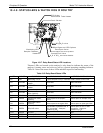
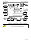
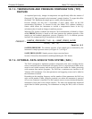
Figure 10-18. Power Distribution Block Diagram
A 6.75 ampere circuit breaker is built into the ON/OFF switch. In case of a wiring fault
or incorrect supply power, the circuit breaker will automatically turn off the analyzer.
CAUTION
Should the power circuit breaker trip, correct the condition causing this
situation before turning the analyzer back on.
07266B DCN6485