


Principles Of Operation Model T101 Instruction Manual
262
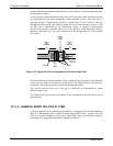
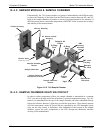
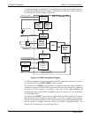
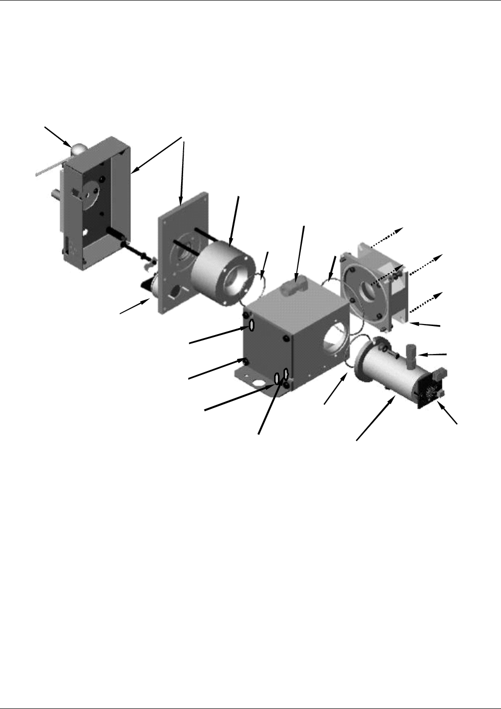
10.4.2. SENSOR MODULE & SAMPLE CHAMBER
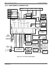
Electronically, the T101 sensor module is a group of subassemblies with different tasks:
to detect the intensity of the light from the fluorescence reaction between SO
2
and UV
light in the sample chamber, to produce a current signal proportional to the intensity of
the fluorescence and to control the temperature of the PMT cooler to ensure the accuracy
and stability of the measurements.
UV Source Lamp
Shutter Housing
Shutter Assy
(hidden from view)
UV Source Lens &
Housing
PMT Lens
Housing
Sample Chamber
Sample Chamber
Heater
Sample Chamber
Temperature Sensor
Reference
Detector
Light Trap
Sample Air
Outlet
O-Ring
Sea l
Sample
Air Inlet
Sample Chamber
Heater
O-Ring
Sea l
O
-
Ring
Seal
PMT
Housing
Attaches
Here
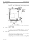
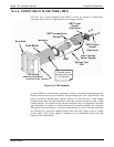
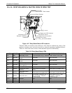
Figure 10-12. T101 Sample Chamber
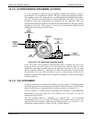
10.4.3. SAMPLE CHAMBER HEATING CIRCUIT
In order to reduce temperature effects, the sample chamber is maintained at a constant
50°C, just above the high end of the instrument’s operation temperature range. Two AC
heaters, one embedded into the top of the sample chamber, the other embedded directly
below the reference detector’s light trap, provide the heat source. These heaters operate
off of the instrument’s main AC power and are controlled by the CPU through a power
relay on the relay board. A thermistor, also embedded in the bottom of the sample
chamber, reports the cell’s temperature to the CPU through the thermistor interface
circuitry of the motherboard.
07266B DCN6485