


Principles Of Operation Model T101 Instruction Manual
268
10.4.9. STATUS LEDS & WATCH DOG CIRCUITRY
Z
ero/Span and IZS Options
S
ample/Cal Valve
IZS Option
Permeation Tube Heater
Dark Shutter
Sample Chamber
Heater
I
2
C
Watchdo
g
LED
Zero/Span and IZS Options
Zero/Span Valve
H
2
S SO
2
converter heater
SO
2
/H
2
S valve
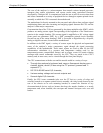
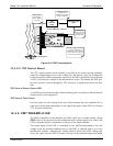
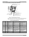
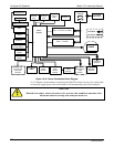
Figure 10-17. Relay Board Status LED Locations
Thirteen LEDs are located on the analyzer’s relay board to indicate the status of the
analyzer’s heating zones and valves as well as a general operating watchdog indicator.
Table 10-2 shows the states of these LEDs and their respective functionality.
Table 10-2. Relay Board Status LEDs
LED COLOR FUNCTION STATUS WHEN LIT STATUS WHEN UNLIT
D1 RED Watchdog circuit Cycles On/Off every 3 seconds under control of the CPU.
D2 YELLOW
Sample chamber
heater
HEATING NOT HEATING
D3 YELLOW
H
2
S SO
2
converter
heater
HEATING NOT HEATING
D4 YELLOW Unused N/A N/A
D5 YELLOW
IZS heater Perm.
Tube (option)
HEATING NOT HEATING
D6 YELLOW Unused N/A N/A
D7 GREEN
Sample/Cal Valve
(option)
Valve open to zero/span
valve.
Valve open to sample inlet
D8 GREEN
Zero/Span Valve
(option)
Valve open to zero gas inlet Valve open to span gas inlet
D9 GREEN SO
2
/H
2
S valve
Gas stream bypasses H
2
S
SO
2
converter. Analyzer
measuring SO
2
Valve open to H
2
S SO
2
converter. Analyzer
measuring H
2
S.
D10 GREEN Unused N/A N/A
D11 GREEN UV Lamp Shutter Shutter open Shutter closed
D12-14 GREEN Unused N/A N/A
07266B DCN6485