


Teledyne API T/E-Series Models 101, 102, and 108 Software Documentation (PN05492D DCN6485)
A-28
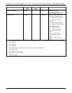
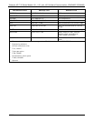
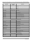
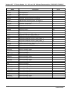
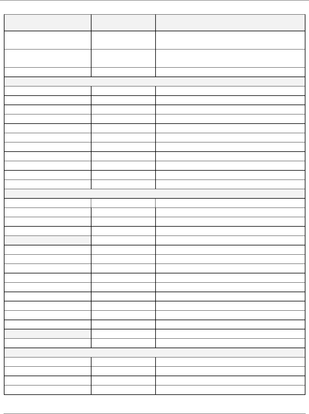
Signal Name
Bit or Channel
Number
Description
DARK_SHUTTER 10 0 = close dark shutter
1 = open
FLUSH_VALVE
4
11 0 = open flow restrictor bypass (flush) valve
1 = close
12–15 Spare
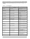
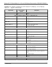
AUX board analog inputs, default I
2
C address 30 hex
PMT_SIGNAL
7
0 (register number) PMT detector
UVLAMP_SIGNAL
7
1 UV lamp intensity
NORM_PMT_SIGNAL
7
2 Normalized PMT detector
PMT_TEMP
7
3 PMT temperature
HVPS_VOLTAGE
7
4 HV power supply output
PMT_DARK
7
5 PMT reading during dark cycles
LAMP_DARK
7
6 Lamp reading during dark cycles
AGND_DARK
7
7 AGND reading during dark cycles
AGND_LIGHT
7
8 AGND reading during light cycles
VREF_DARK
7
9 VREF4096 reading during dark cycles
VREF_LIGHT
7
10 VREF4096 reading during light cycles
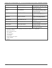
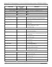
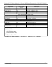
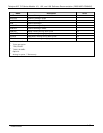
Rear board primary MUX analog inputs
PMT_SIGNAL 0 PMT detector
HVPS_VOLTAGE 1 HV power supply output
PMT_TEMP 2 PMT temperature
UVLAMP_SIGNAL 3 UV lamp intensity
4 Temperature MUX
PHOTO_ABS 5 Pre-amplified UV lamp intensity
OXY_FLOW
2
6 Oxygenator flow rate
SAMPLE_PRESSURE 7 Sample pressure
TEST_INPUT_8 8 Diagnostic test input
REF_4096_MV 9 4.096V reference from MAX6241
SAMPLE_FLOW 10 Sample flow rate
TEST_INPUT_11 11 Diagnostic test input
CONV_TEMP
1
12 Converter temperature
13 Spare (thermocouple input?)
14 DAC MUX
REF_GND 15 Ground reference
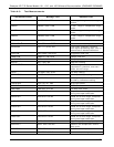
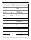
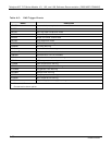
Rear board temperature MUX analog inputs
BOX_TEMP 0 Internal box temperature
RCELL_TEMP 1 Reaction cell temperature
IZS_TEMP 2 IZS temperature
3 Spare
07266B DCN6485