


Principles Of Operation Model T101 Instruction Manual
256
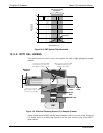
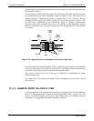
pressure differential combined with the action of the analyzer’s external pump draws the
gas through the orifice.
As the pressure on the downstream side of the orifice (the pump side) continues to drop,
the speed that the gas flows though the orifice continues to rise. Once the ratio of
upstream pressure to downstream pressure is greater than 2:1, the velocity of the gas
through the orifice reaches the speed of sound. As long as that ratio stays at least 2:1 the
gas flow rate is unaffected by any fluctuations, surges, or changes in downstream
pressure because such variations only travel at the speed of sound themselves and are
therefore cancelled out by the sonic shockwave at the downstream exit of the critical
flow orifice.
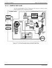
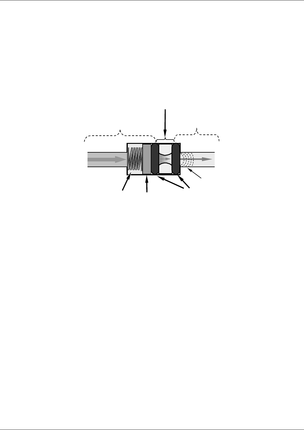
SPRING
O-RINGS
FILTER
CRITICAL
FLOW
ORIFICE
A
REA OF
LOW
PRESSURE
AREA OF
HIGH
PRESSURE
Sonic
Shockwave
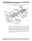
Figure 10-8. Typical Flow Control Assembly with Critical Flow Orifice
The actual flow rate of gas through the orifice (volume of gas per unit of time), depends
on the size and shape of the aperture in the orifice. The larger the hole, the more gas
molecules, moving at the speed of sound, pass through the orifice.
The result is that he flow rate of the gas is unaffected by degradations in pump
efficiency due to age.
The critical flow orifice used in the Model T101 is designed to provide a flow rate of
600 cm3/min.
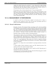
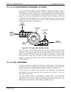
10.3.4. SAMPLE PARTICULATE FILTER
To remove particles in the sample gas, the analyzer is equipped with a Teflon membrane
filter of 47 mm diameter (also referred to as the sample filter) with a 1 µm pore size. The
filter is accessible through the front panel, which folds down, and should be changed
according to the suggested maintenance schedule in Table 9-1.
07266B DCN6485