Teledyne API – T101 Operation Manual Operating Instructions
103
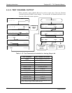
Once a TEST function is selected, the instrument begins to report a signal on the A4
output and adds TEST= to the list of test functions viewable on the display (just before
the TIME display).
4.7. SETUP – COMM: SETTING UP THE ANALYSER’S
COMMUNICATION PORTS
For remote operation the T101 is equipped with an Ethernet port, a USB port and two
serial communication (com) ports located on the rear panel. Both com ports (labeled
RS232, which is the COM1 port, and COM2) operate similarly and give the user the
ability to communicate with, issue commands to, and receive data from the analyzer
through an external computer system or terminal. By default, both ports operate on the
RS-232 protocol.
The RS232 port can also be configured to operate in single or RS-232 Multidrop mode
(Option 62). The COM2 port can be left in its default configuration for standard RS-232
operation, or reconfigured for half-duplex RS-485 operation; (contact the factory for
configuration information). When COM2 is configured for RS-485 communication, the
rear panel USB port is disabled.
A code-activated switch (CAS), can also be used on either port to connect typically
between 2 and 16 send/receive instruments (host computer(s) printers, data loggers,
analyzers, monitors, calibrators, etc.) into one communications hub. Contact Teledyne
API’s Sales for more information on CAS systems.
4.7.1. INSTRUMENT ID
Each type of Teledyne API’s analyzer is configured with a default ID code. The default
ID code for all T101 analyzers is either “0” or 101. The ID number is only important if
more than one analyzer is connected to the same communications channel such as when
several analyzers are on the same Ethernet LAN, in a RS-232 Multidrop chain, or
operating over a RS-485 network. If two analyzers of the same model type are used on
one channel, the ID codes of one or both of the instruments needs to be changed so that
they are unique to the instruments.
07266B DCN6485


