


TABLE OF CONTENTS Teledyne API – T101 Operation Manual
xvi
Figure 10-8. Typical Flow Control Assembly with Critical Flow Orifice ..................................... 256
Figure 10-9. T101 Hydrocarbon Scrubber (Kicker) .............................................................. 257
Figure 10-10. T101 Electronic Block Diagram ..................................................................... 259
Figure 10-11. T101 CPU Board ......................................................................................... 261
Figure 10-12. T101 Sample Chamber................................................................................ 262
Figure 10-13. PMT Assembly............................................................................................ 263
Figure 10-14. Basic PMT Design ....................................................................................... 264
Figure 10-15. PMT Cooling System ................................................................................... 265
Figure 10-16. PMT Preamp Block Diagram ......................................................................... 266
Figure 10-17. Relay Board Status LED Locations................................................................. 268
Figure 10-18. Power Distribution Block Diagram ................................................................. 272
Figure 10-19. Front Panel and Display Interface Block Diagram............................................. 273
Figure 10-20. Basic Software Operation............................................................................. 274
Figure 11-1. Triboelectric Charging ................................................................................... 277
Figure 11-2. Basic anti-ESD Work Station .......................................................................... 280
LIST OF TABLES
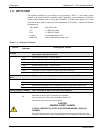
Table 1-1. Analyzer Options............................................................................................... 20
Table 2-1. Model T101 Basic Unit Specifications.................................................................... 23
Table 3-1. Display Screen and Touch Control Description ....................................................... 28
Table 3-2. Rear Panel Description ....................................................................................... 31
Table 3-3. Analog Input Pin Assignments............................................................................. 34
Table 3-4. Analog Output Pin Assignmentss ......................................................................... 35
Table 3-5. Status Output Signals........................................................................................ 37
Table 3-6. Control Input Signals......................................................................................... 38
Table 3-7. Inlet / Outlet Connector Descriptions ................................................................... 40
Table 3-8. H
2
S – SO
2
Switching Valve Operating States ......................................................... 42
Table 3-9. NIST-SRM's Available for Traceability of H
2
S & SO
2
Calibration Gases ....................... 44
Table 3-10. Zero/Span Valve Operating States ..................................................................... 46
Table 3-11. IZS Valve Operating States............................................................................... 49
Table 3-12. Possible Warning Messages at Start-Up .............................................................. 51
Table 4-1. Analyzer Operating Modes .................................................................................. 57
Table 4-2. Test Functions Defined....................................................................................... 59
Table 4-3. List of Warning Messages ................................................................................... 61
Table 4-4. Primary Setup Mode Features and Functions ......................................................... 64
Table 4-5. Secondary Setup Mode Features and Functions ..................................................... 64
Table 4-6. Password Levels............................................................................................... 74
Table 4-7. Variable Names (VARS)...................................................................................... 77
Table 4-8. T101 Diagnostic (DIAG) Functions ....................................................................... 81
Table 4-9. DIAG - Analog I/O Functions............................................................................... 85
Table 4-10. Analog Output Voltage Ranges .......................................................................... 85
Table 4-11. Analog Output Current Loop Range .................................................................... 86
Table 4-12. Analog Output Pin Assignments ......................................................................... 86
Table 4-13. Voltage Tolerances for Analog Output Calibration ................................................. 90
07266B DCN6485