


4/00 UDC 3300 Process Controller Product Manual 95
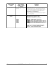
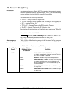
Lower Display
Prompt
Upper Display
Range of Setting
or Selection
Parameter
Definition
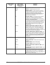
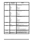
PID A
ATTENTION
PID A should
not be used for Proportional
only action; i.e., no integral
(reset) action. Instead, use
PD+MR with rate set to 0.
PID A is normally used for three-mode control. This means
that the output can be adjusted somewhere between 100
% and 0 %. It applies all three control actions—
Proportional (P), Integral (I), and Derivative (D)—to the
error signal.
Proportional (Gain)
—Regulates the controller’s output in
proportion to the error signal (the difference between
Process Variable and Setpoint).
Integral (Reset
)—Regulates the controller’s output to the
size of the error and the time the error has existed. (The
amount of corrective action depends on the value of
proportional Gain.)
Derivative (Rate)
—Regulates the controller’s output in
proportion to the rate of change of the error. (The amount
of corrective action depends on the value of proportional
Gain.)
PID B PID B—Unlike the PID A equation, the controller gives
only an integral response to a setpoint change, with no
effect on the output due to the gain or rate action, and it
gives full response to PV changes. Otherwise controller
action is as described for the PID A equation. See note on
PID A.
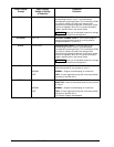
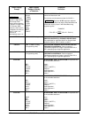
PD+MR PD WITH MANUAL RESET is used whenever integral
action is not wanted for automatic control. The equation is
computed with no integral contribution. The MANUAL
RESET, which is operator adjustable, is then added to the
present output to form the controller output.
Switching between manual and automatic mode will be
bumpless.
If you select PD with Manual Reset you can also configure
the following variations
• PD (Two Mode) control,
• P (Single Mode) control.
Set Rate (D) to 0.
Other prompts affected: MANRSET3
OUT OVRD
OUTPUT OVERRIDE SELECT—This selection lets you
select high or low output override. Only available if the
controller is configured for 2-Loop operation. (NOTE 1)
ATTENTION
Loop 1 must be in Automatic for this
selection to work. While the output is being overridden, an
“O” appears as the leftmost digit of the upper display.
DISABL DISABLE—Disables Output Override.
HI SEL HIGH SELECT—The controller will select the higher of
output 1 or output 2 and direct it to output 1 rear terminals.
LO SEL LOW SELECT—The controller will select the lower of
output 1 or output 2 and direct it to output 1 rear terminals.