


4/00 UDC 3300 Process Controller Product Manual 223
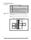
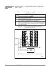
7.4 Input #1, #2, or #3 Set Up Wiring
Thermocouple inputs
using an ice bath
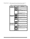
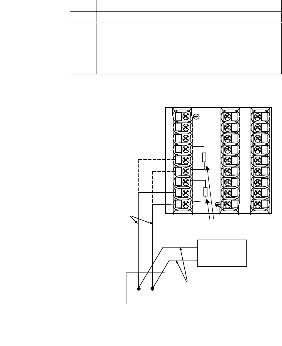
Referring to Figure 7-2, wire the controller according to the procedure
given in Table 7-3.
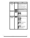
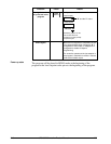
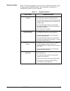
Table 7-3 Set Up Wiring Procedure for Thermocouple Inputs Using an
Ice Bath
Step Action
1
Connect the copper leads to the calibrator.
2
Connect a length of thermocouple extension wire to the end of each copper
lead and insert the junction points into the ice bath.
3
Connect the thermocouple extension wires to the terminals for Input #1 or
Input #2. See Figure 7-2.
4
Connect a cold junction resistor to terminals 25 and 27 for Input #1 or
terminals 22 and 24 for Input #2. See Figure 7-2.
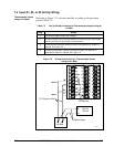
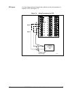
Figure 7-2 Wiring Connections for Thermocouple Inputs
Using an Ice Bath
1
2
3
4
5
6
7
8
9
10
11
12
13
14
15
16
17
L1
L2/N
22
23
24
25
26
27
+
–
Ice Bath
Millivolt
Source
T/C Extension Wire
Copper Leads
+
–
24174
C/J Resistor
+
–
Input 2
Input 1