


28 UDC 3300 Controller Product Manual 4/00
Position proportional
output connections
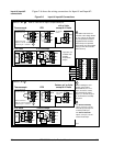
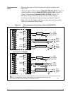
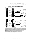
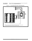
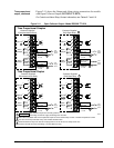
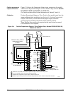
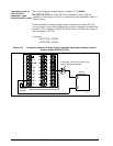
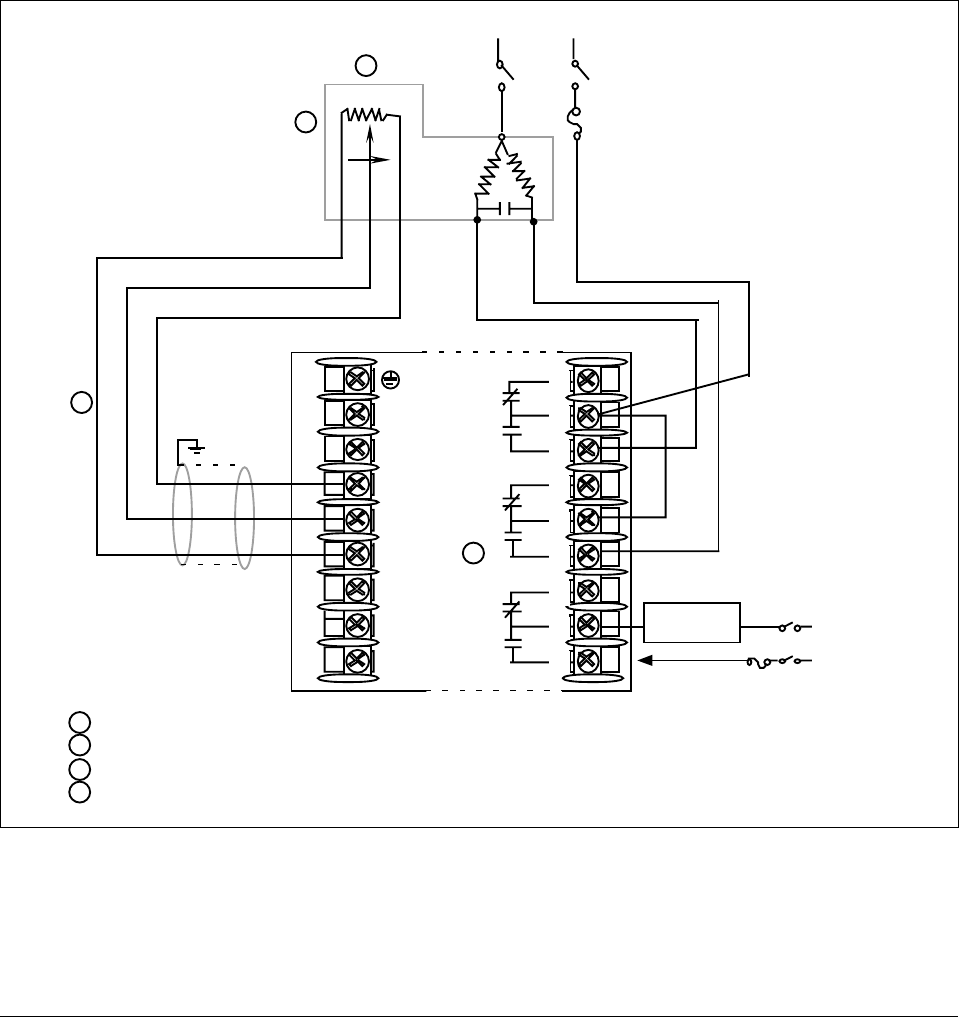
Figure 2-14 shows the Output and Alarm wiring connections for models
with Position Proportional Output or Three Position Step Control (Models
DC330X-EE-XXX-X2, DC330X-AA-XXX-X2).
For Control and Alarm Relay Contact information, see Tables 2-7 and 2-8.
Calibration
Position Proportional Output or Three Position Step models must have the
output calibrated after installation (see Section 8—Position Proportional
Output Calibration) to ensure that the displayed output (slidewire
position) agrees with the actual final control element position.
Three Position Step models only require that the motor time be entered.
Full calibration is not required.
Figure 2-14 Position Proportional Output or Three Position Step—Models DC330X-EE-XXX-X2,
DC330X-AA-XXX-X2
L1
L2/N
22
23
24
25
26
27
Slidewire 100 to 1000 Ω
mechanically linked
to motor
Connect shield to ground
at one end only
Neutral Hot
Motor Power
Supply
Open Closed
To terminal
7 or 9
Open
Alarm
Relay#1
Output
Relay#1
Output
Relay#2
N.C.
N.C.
N.O.
N.O.
N.C.
N.O.
Closed
Wiper
2
1
1
2
3
Alarm #2 is not available with Position Proportional output or Three Position Step control.
Do not run slidewire cable in the same conduit as AC power.
Electrical noise suppression may be required. Refer to Section 12.
Slidewire input is not required for Three Position Step control but can be used for motor position indication.
4
3
4
Alarm Relay
#1 Load
Load
Supply
Power
24168
5 Amp Fast Blo fuse
5 Amp Fast Blo fuse
1
2
3
4
5
6
7
8
9