


172 UDC 3300 Controller Product Manual 4/00
5.12 Two Loops of Control Overview
Introduction
The UDC 3300 can operate using two independent loops of control or
internal Cascade control.
Available only on Expanded Model DC330E-XX-XXX.
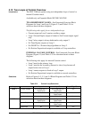
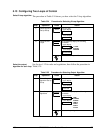
TWO INDEPENDENT LOOPS—See Functional Overview Block
Diagrams for Loop 1 and Loop 2 (Figure 5-2) and Table 5-21 for
selections based on these diagrams.
The following rules apply for two independent loops:
• Current output on Loop 2 requires auxiliary output.
• Loop 2 Current Duplex output is limited to 2nd Current output signal
only.
• Loop 2 relay output is always dedicated to relay output 2.
• No Time Duplex outputs on Loop 2.
• No ON/OFF or 3 Position Step algorithms on Loop 2.
• No Position Proportional output is available on 2-loop controllers.
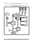
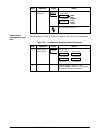
INTERNAL CASCADE CONTROL—See Functional Overview Block
Diagram (Figure 5-3) and Table 5-25 for selections based on these
diagrams.
The following rules apply for internal Cascade control:
• Loop 2 must be the primary loop.
• Loop 1 must be the secondary (internal or slave) loop because all
output forms exist on Loop 1.
• Loop 1 remote setpoint is fixed as Loop 2 output.
• No Position Proportional output is available on cascade controllers.
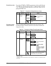
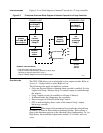
Selections
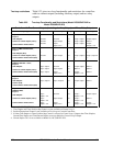
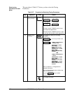
Refer to Figures 5-2, 5-3, and 5-4 Block Diagrams and Table 5-21 for
selections based on these diagrams.
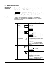
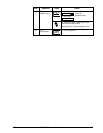
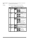
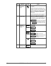
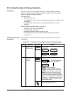
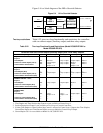
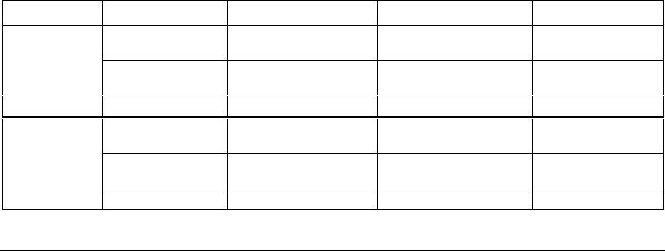
Table 5-21 Control Loop Selections
Loop Input 1 Input 2 Input Algorithm
LOOP 1
Process Variable* Via Configuration or
Digital Inputs
Via Configuration or
Digital Inputs
Yes
Remote Setpoint No Via configuration or
Digital Inputs
Yes
Feedforward No Yes Yes
LOOP 2
Process Variable* Via Configuration or
Digital Inputs
Via Configuration or
Digital Inputs
Yes
Remote Setpoint No Via Configuration or
Digital Inputs
Yes
Feedforward No Yes Yes
*The PV may be a combination of multiple inputs via a Loop input algorithm.