


230 UDC 3300 Process Controller Product Manual 4/00
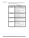
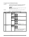
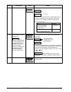
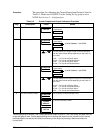
Step Description Press Action
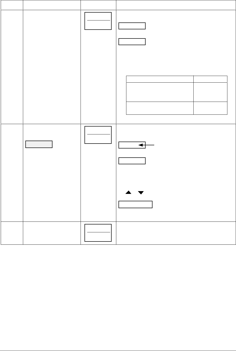
3
Calibrate 100 %
FUNCTION
LOOP 1/2
You will see:
INn SPAN
Lower Display
APPLY
Upper Display
n = 1, 2, or 3
Adjust your calibration device to an output signal equal to
the 100 % range value for your particular input sensor.
See Table 7-1 for Voltage or Resistance equivalents.
Wait 15 seconds, and
If… Then…
you are calibrating a Go to step 4
thermocouple input
(Input 1 or 2)
you are calibrating other Go to step 5
than a thermocouple input
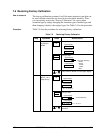
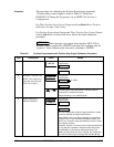
4
Check the Cold Junction
Temperature
CAUTION
The
accuracy of the controller
is directly affected by the
accuracy of this value.
Change this value only if
the zero and span
calibration procedures did
not bring the controller
within the specified
accuracy requirements.
FUNCTION
LOOP 1/2
The calculations for zero and span are now stored and
you will see:
Lower Display
Upper Display
C-J TEMP
The cold junction
temperature at the
rear terminals
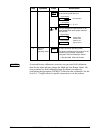
The value in the upper display is in the tenths of a degree.
It is the current reading of the temperature as measured at
the thermocouple terminals and recognized by the
controller. You can change this value, if it is in error, using
the
or
key.
ATTENTION
When calibrating T/C inputs using a
precision 500-ohm resistor, calibrate the cold junction as
77°F (25°C).
5
Exit the Calibration Mode
FUNCTION
LOOP 1/2
The controller will store the calibration constants and exit
calibration mode.