


124 UDC 3300 Process Controller Product Manual 4/00
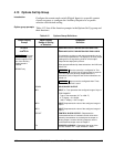
4.12 Loop 2 Control Parameters Set Up Group
Introduction
The functions listed in this group deal with how Loop 2 of a Two-Loop
process controller will control the process including: PV source, Number
of tuning parameter sets, Setpoint source, Tracking, Power-up recall,
Setpoint limits, Output direction, rate and limits, Dropoff, Deadband, and
Hysteresis.
Only available on Expanded Model DC330E-XX-XXX.
Control 2 group
prompts
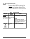
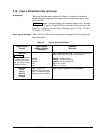
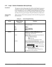
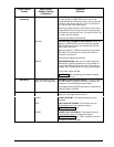
Table 4-11 lists all the function prompts in the Control 2 Set Up group and
their definitions.
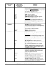
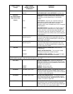
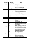
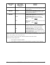
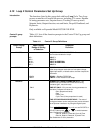
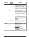
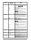
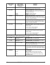
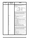
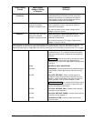
Table 4-11 Control 2 Group Definitions
Lower Display
Prompt
Upper Display
Range of Setting
or Selection
Parameter
Definition
PV 2 SRC
INP 1
INP 2
IN AL1
IN AL2
INP 3
PROCESS VARIABLE 2 SOURCE—Select the source of
the Process Variable for Loop 2.
INPUT 1
INPUT 2
INPUT ALGORITHM 1
INPUT ALGORITHM 2
INPUT 3
FORCE MA
DISABL
LINK12
FORCE MANUAL/AUTO links Auto/Manual modes. If
either loop changes mode due to a front panel change,
digital input action, or failsafe action, the other loop tracks
that mode.
DISABL—Disables FORCE MA.
LINK12—Links modes for both loops.
PID SETS
NUMBER OF TUNING PARAMETER SETS—This
selection lets you choose one or two sets of tuning
constants (gain, rate, and reset).
1 ONLY ONE SET ONLY—Only one set of tuning parameters is
available. Configure the values for:
Gain (proportional band)
Rate
Reset Time
Cycle Time (if time proportional is used)
2KEYBD TWO SETS KEYBOARD SELECTABLE—Two sets of
tuning parameters can be configured and can be selected
at the operator interface or by using the Digital Inputs.
Press LOWER DISPLAY
key until you see PID SET3 or
PID SET4 then press
or to switch between
sets. Configure the values for:
Gain #3, Rate #3 , Reset #3, Cycle #3 Time
Gain #4, Rate #4, Reset #4, Cycle #4 Time
See Subsection 5.10 for procedure.