


4/00 UDC 3300 Controller Product Manual 241
Procedure
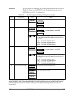
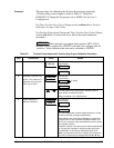
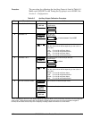
The procedure for calibrating the Auxiliary Output is listed in Table 8-5.
Make sure LOCKOUT in the Tuning Set Up group is set to NONE. See
Section 3 – Configuration.
Table 8-5 Auxiliary Output Calibration Procedure
Step Description Press Action
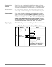
1
Enter Calibration Mode
SET UP
until you see
AUX OUT
Lower Display
CALIB
Upper Display
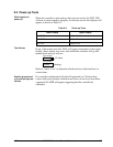
2
Calibrate 0 %
FUNCTION
LOOP 1/2
You will see:
Lower Display
Upper Display
ZERO VAL
a value between 0 and 4095
or
until the desired 0 % output is read on the milliammeter.
Use the values shown below depending on the action of
your valve.
0 mA For 0 to 20 mA Direct Action *
20 mA For 0 to 20 mA Reverse Action
4 mA For 4 to 20 mA Direct Action
20 mA For 4 to 20 mA Reverse Action
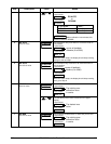
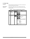
3
Calibrate 100 %
FUNCTION
LOOP 1/2
This stores the 0 % value and you will see:
Lower Display
Upper Display
SPAN VAL
a value
or
until the desired 100 % output is read on the milliammeter.
Use the values shown below depending on the action of
your valve.
20 mA For 0 to 20 mA Direct Action
0 mA For 0 to 20 mA Reverse Action*
20 mA For 4 to 20 mA Direct Action
4 mA For 4 to 20 mA Reverse Action
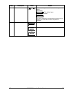
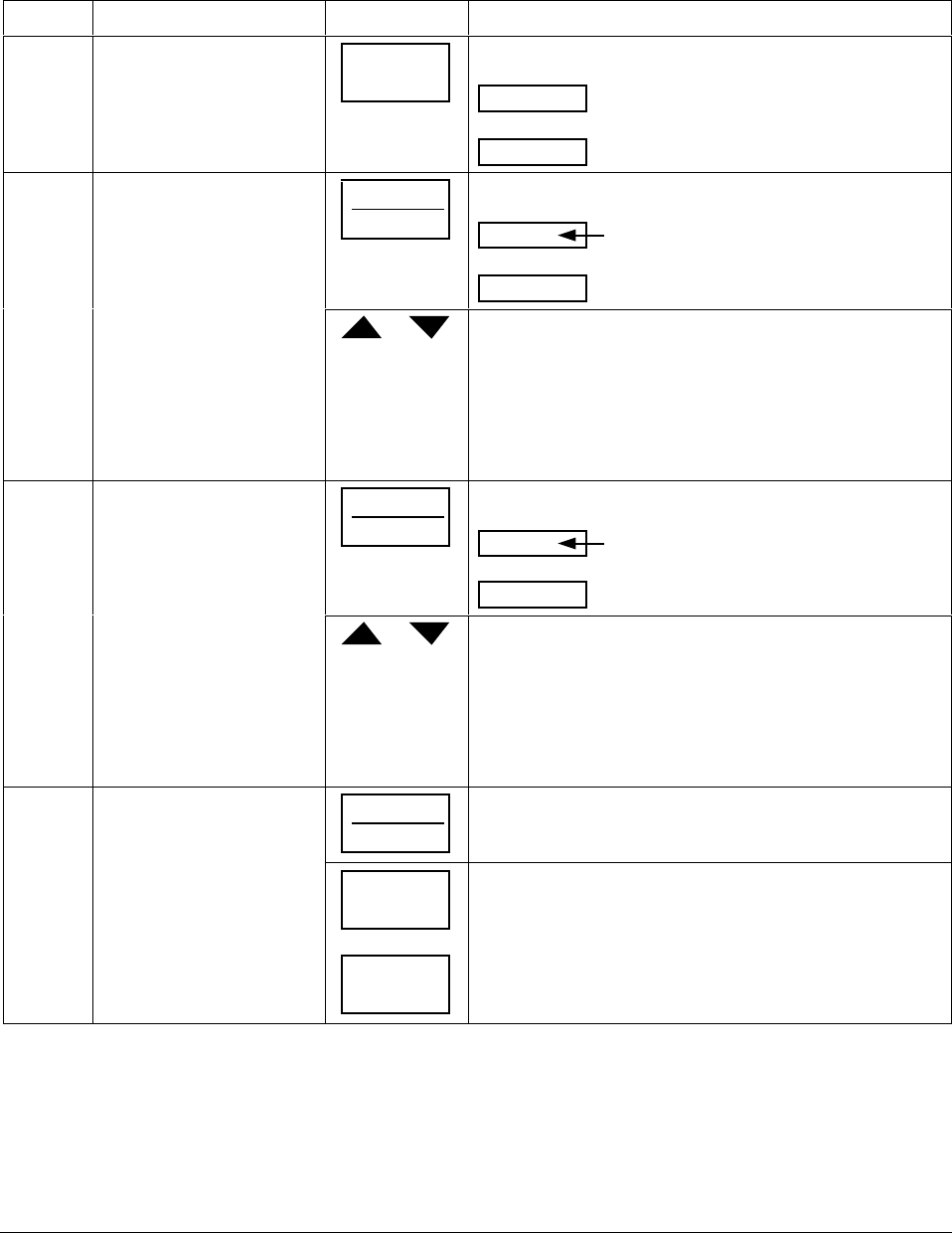
4
Exit the Calibration Mode
FUNCTION
LOOP 1/2
The controller will store the span value.
LOWER
DISPLAY
or
SET UP
To exit the calibration mode.
*When attempting to achieve 0 mA, always adjust the output to about 0.5 mA, and slowly decrease until the output just
goes to zero. Further decrementing will not change the output current (since the circuit cannot produce negative
current) but will affect the accuracy of the output by creating a dead zone where no current flows.