


240 UDC 3300 Controller Product Manual 4/00
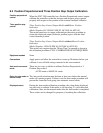
8.4 Auxiliary Output Calibration
Introduction
Calibrate the controller so that the Auxiliary output provides the proper
amount of current over the desired range. The controller can provide an
auxiliary output current range of from 0 to 21 milliamperes and can be
calibrated at 4 mA for 0 % of output and 20 mA for 100 % of output or
any other values between 0 mA and 21 mA.
Equipment needed
You will need a standard shop type milliammeter with whatever accuracy
is required, capable of measuring 0 to 20 milliamps.
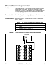
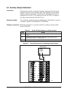
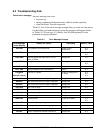
Calibrator connections
Referring to Figure 8-2, wire the controller according to the procedure
given in Table 8-4.
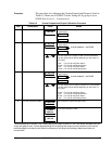
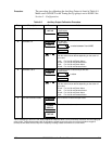
Table 8-4 Set Up Wiring Procedure for Auxiliary Output
Step Action
1
Apply power and allow the controller to warm up 30 minutes before you
calibrate.
2
Tag and disconnect the field wiring, at the rear of the controller, from
terminals 16 (+) and 17 (–). See Figure 8-2.
3
Connect a milliammeter across these terminals.
Figure 8-2 Wiring Connections for Calibrating Auxiliary Output
1
2
3
4
5
6
7
8
9
10
11
12
13
14
15
16
17
L1
L2/N
22
23
24
25
26
27
–
Milliammeter
+
–
+
22636