


4 UDC 3300 Controller Product Manual 4/00
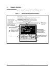
Function of keys
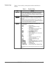
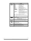
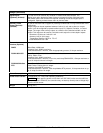
Table 1-1 shows each key on the operator interface and defines its
function.
Table 1-1 Function of Keys
Key Function
SET UP • Places the controller in the Configuration Set Up group
select mode. Sequentially displays Set Up groups and
allows the FUNCTION key to display individual functions in
each Set Up group.
FUNCTION
LOOP 1/2
• Used in conjunction with the SET UP key to select the
individual functions of a selected Configuration Set Up
group.
• Used to switch the display between Loop 1 and Loop 2
when the controller has a 2-Loop or Cascade configuration.
• Used during field calibration procedure.
LOWER
DISPLAY
• Selects an operating parameter to be shown in the
lower display:
OUT = Output
(Note 1)
OT2 = Output 2 (Cascade or 2-Loop
applications
SP = Local Setpoint
(also current SP value
when using SP ramp) (Note 2)
2SP = Local Setpoint 2 (Note 2)
3SP = Local Setpoint 3 (Note 2)
RSP = Remote Setpoint
1IN = Input 1
—when used with combinational
input algorithms
2IN = Input 2
3IN = Input 3
POS =
3 Position Step motor position when
slidewire is connected
CSP = Computer Setpoint Override
DEV = Deviation
PIDSETX = Tuning Parameter Set
X=1 or 2 (Note 3)
2PIDSETX = Loop 2 Tuning Parameter Set X=1 or 2
ET_XX.XX = Elapsed Time
TR_XX.XX = Time Remaining
RAMPXXOM = Minutes Remaining in Setpoint Ramp
*Or estimated Three Position Step motor position when no slidewire
exists.