


4/00 UDC 3300 Controller Product Manual 269
MCU/output board
Follow the procedure listed in Table 9-23 to replace the following
MCU/output boards:
Basic
• Current Output—P/N 51309401-504
• Relay Output—P/N 51309401-505
Expanded
• Current Output—P/N 51309401-504
• Relay Output—P/N 51309401-505
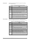
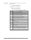
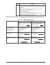
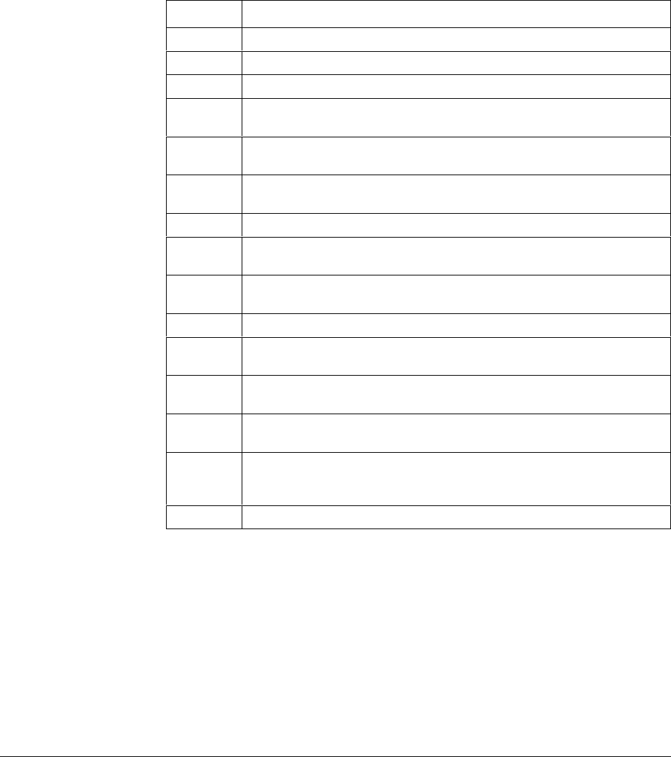
Table 9-23 MCU/Output Board Replacement Procedure
Step Action
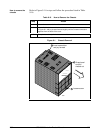
1
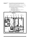
Remove the chassis from the case. See Figure 9-1.
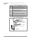
2
Remove the printed wiring boards from the chassis. See Figure 9-3.
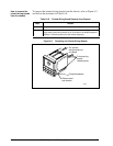
3
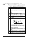
Lay the boards flat and identify the MCU/Output board. See Figure 9-4.
4
Each option board is held onto the MCU/Output board with three posts.
Locate these posts under the MCU/Output board.
5
Use small pliers and squeeze the ends of each post together and push it
up through the board. Remove the option boards present.
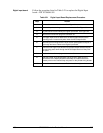
6
Remove the transformer connections to the Digital Input board and the
Auxiliary Output/Communications board, if present.
7
Remove the Digital Input Board, if present. See Table 9-21.
8
Remove the Auxiliary Output/Communications board, if present. See
Table 9-22.
9
Remove the connector from plug WG. Slide a small screwdriver under the
connector and lift the release.
10
Replace the MCU/Output board.
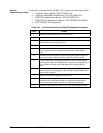
11
Reinstall the Digital Input board, if present, onto the new MCU/Output
board.
12
Reinstall the Auxiliary Output/Communications board, if present, onto the
new MCU/Output board.
13
Reinstall the WG connector and the transformer connectors to the Digital
Input board and Auxiliary Output/Communications board, if present.
14
Slide the printed wiring boards back into the chassis. Make sure the
connections to the display/keyboard assembly are made and that the
release points on the chassis snap into place on the printed wiring boards.
15
Reinstall the chassis into the case. Push in hard, then tighten the screw.