16 UDC 3300 Controller Product Manual 4/00
Permissible wire
bundling
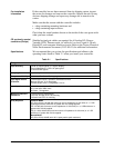
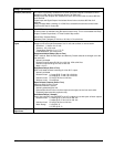
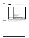
Table 2-3 shows which wire functions should be bundled together.
NOTE
For installation where high EMI/RFI noise cannot be avoided, we
recommend you use shielded twisted pair wires for the signals in bundle 2.
Table 2-3 Permissible Wiring Bundling
Bundle No. Wire Functions
1 • Line power wiring
• Earth ground wiring
• Control relay output wiring
• Line voltage alarm wiring
2 Analog signal wire, such as:
• Input signal wire (thermocouple, 4 to 20 mA, etc.)
• 4-20 mA output signal wiring
• Slidewire feedback circuit wiring
• Digital input signals
• Communications
3 • Low voltage alarm relay output wiring
• Low voltage wiring to solid state type control circuits
Identify your wiring
requirements
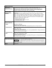
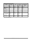
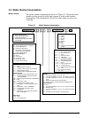
To determine the appropriate diagrams for wiring your controller, refer to
the model number interpretation in this section. The model number of the
controller can be found on the inside of the case.


