


266 UDC 3300 Controller Product Manual 4/00
2nd input board
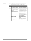
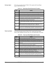
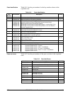
Follow the procedure listed in Table 9-19 to replace the Second Input
board—P/N 30756715-501.
Table 9-19 Second Input Board Replacement Procedure
Step Action
1
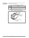
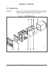
Remove the chassis from the case. See Figure 9-1.
2
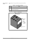
Remove the printed wiring boards from the chassis. See Figure 9-3.
3
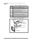
Lay the boards flat and identify the 2nd Input board. See Figure 9-4.
4
Remove the transformer plug from connector J14.
5
The 2nd Input board is attached to the Power Input board by three
mounting posts. Locate these posts under the power input board.
6
Use a small pliers and squeeze the ends of each post together and push it
up through the board. Remove 2nd Input board.
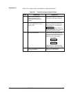
7
Orient the new 2nd Input board onto the Power Input board and push the
mounting posts down through the Power Input board until they click into
place.
8
Replace the transformer plug onto connector J14. Make sure the Input 2
jumper (W1/W2) is in the correct position. (Refer to Table 2-4.)
9
Slide the printed wiring boards back into the chassis. Make sure the
connections to the display/keyboard assembly are made and that the
release points on the chassis snap into place on the printed wiring boards.
10
Reinstall the chassis into the case. Push in hard, then tighten screw.
Power input board
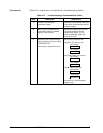
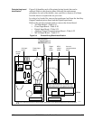
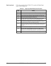
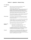
Follow the procedure listed in Table 9-20 to replace the Power Input
board—P/N 51309404-502 (90 to 264 Vac) or 51309404-501 (24 Vac/dc).
Table 9-20 Power Input Board Replacement Procedure
Step Action
1
Remove the chassis from the case. See Figure 9-1.
2
Remove the printed wiring boards from the chassis. See Figure 9-3.
3
Lay the boards flat and identify the Power Input board. See Figure 9-4.
4
Remove the 2nd Input board, if present. See procedure in
Table 9-19.
5
Remove the transformer connections to the Digital Input board and
Auxiliary Output/Communications board, if present.
6
Remove the connector from plug WG if present (current output models
only). Slide a small screwdriver under the connector and lift the release.
7
Replace the Power Input board.
8
Reinstall WG connector and transformer connections to Digital Input board
and Auxiliary Output/Communications board, if present.
9
Reinstall the 2nd Input board. See procedure in Table 9-19.
10
Slide the printed wiring boards back into the chassis. Make sure the
connections to the display/keyboard assembly are made and that the
release points on the chassis snap into place on the printed wiring boards.
11
Reinstall the chassis into the case. Push in hard, then tighten screw.