


20 UDC 3300 Controller Product Manual 4/00
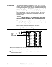
Input #1/Input #2
connections
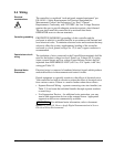
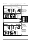
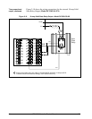
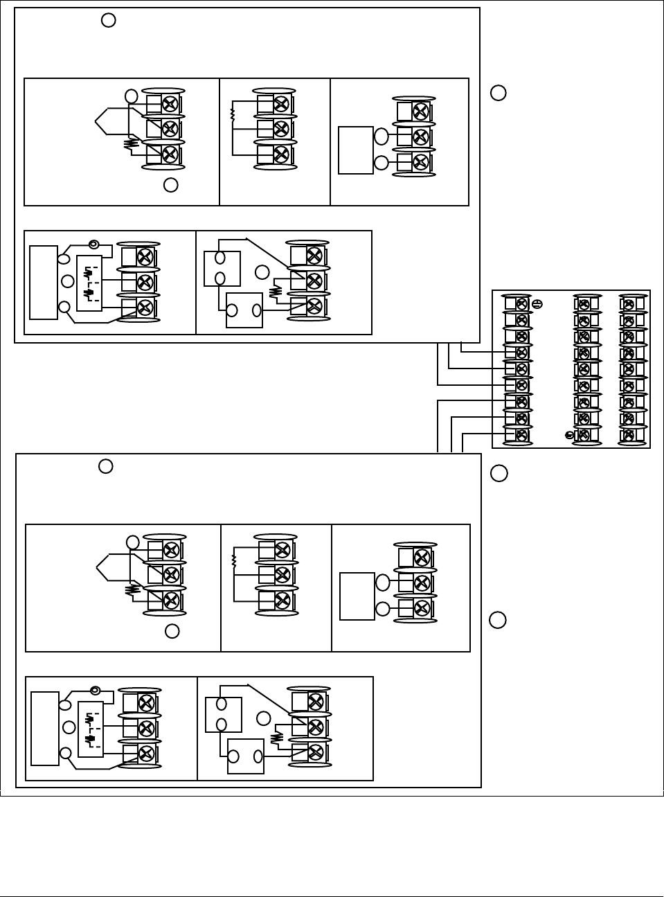
Figure 2-6 shows the wiring connections for Input #1 and Input #2.
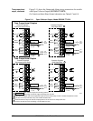
Figure 2-6 Input #1/Input #2 Connections
25
26
27
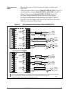
Use Thermocouple
extension wire only
Thermocouple
RTD
Carbon, mV or Volts
except 0-10 Volts
mV or Volt
source
0-10 Volts 4-20 milliamps
–
+
+
R
–
1
2
3
–
0–10
Volt
source
+
100K
100K
Power
Supply
–+
Xmitter
+
–
250Ω
1
Remove screw and
install C/J on the "R" terminal,
connect tang to "–" terminal.
2
25
26
27
+
R
–
25
26
27
+
R
–
25
26
27
+
R
–
1
25
26
27
+
R
–
1
INPUT #1
3
R
+
–
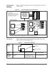
The 250Ω load resistor for
4-20 mA or the voltage divider
for 0-10 volts or the 500 ohm
C/J compensation resistor is
supplied with the controller
when the input is specified.
These items must be installed
when you wire the controller
before start-up.
1
2
When installing the cold
junction (Part number
30757088-001) for a T/C
input, remove the screws
from terminals 25 and 27
(Input 1) or 22 and 24 (Input
2), and install the assembly
into place.
24159
3
For Relative Humidity
option, use Input 1 as the
wet bulb input and Input 2
and the dry bulb input.
For Carbon Potential
option, use Input 1 as the
Carbon Probe input.
1
2
3
4
5
6
7
8
9
10
11
12
13
14
15
16
17
L1
L2/N
22
23
24
25
26
27
22
23
24
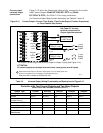
Use Thermocouple
extension wire only
Thermocouple
RTD
mV or Volts
except 0-10 Volts
Carbon, mV
or Volt
source
0-10 Volts 4-20 milliamps
–
+
+
R
–
1
2
3
–
0–10
Volt
source
+
100K
100K
Power
Supply
–+
Xmitter
+
–
250Ω
1
Remove screw and
install C/J on the "R" terminal,
connect tang to "–" terminal.
2
22
23
24
+
R
–
22
23
24
+
R
–
22
23
24
+
R
–
1
22
23
24
+
R
–
1
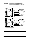
INPUT #2
3
Input #2 is not
available with
Position
Proportional
Output.
R
+
–
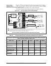
Refer to Table 2-4 for Input 2 Jumper selections.
mV or Volt
source
Carbon,
mV or Volt
source
For Relative Humidity
option, use Input 1 as the
wet bulb input and Input 2
as the dry bulb input.
For Carbon Potential
option, use Input 1 as the
Carbon Probe input.