


4/00 UDC 3300 Controller Product Manual 179
Select tuning
parameters for each
group
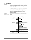
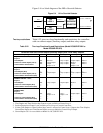
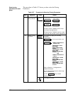
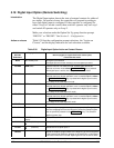
The procedure in Table 5-27 shows you how select the Tuning
Parameters.
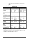
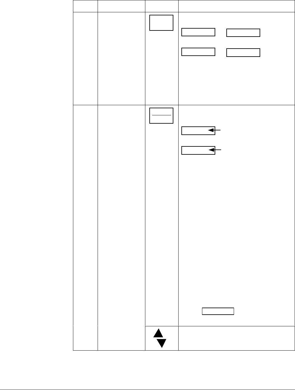
Table 5-27 Procedure for Selecting Tuning Parameters
Step Operation Press Action
1
Select Tuning
Set Up Group
SET UP
until you see:
TUNING
Lower Display
SET UP
Upper Display
TUNING 2
Lower Display
SET UP
Upper Display
for Loop 1 for Loop 2or
PID sets 1 and 2 (TUNING) are for Loop 1
and single loop applications.
PID sets 3 and 4 (TUNING 2) are for Loop 2
in two-loop and cascade control applications.
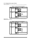
2
Select Tuning
constants
FUNCTION
LOOP 1/2
to successively display the following
constants:
Lower Display
Upper Display
TUNING CONSTANTS for
Primary Loop
PROP BAND or GAIN
RATE (MIN)
RESET (MIN OR RPM)
CYCLE
PROP BAND2 or GAIN2
RATE2 (MIN)
RESET2 (MIN OR RPM)
CYCLE2
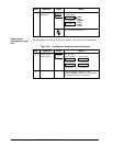
The Tuning Constant Value
TUNING CONSTANTS for
LOOP 2
PROP BAND3 or GAIN3
RATE3 (MIN)
RESET3 (MIN OR RPM)
CYCLE3
PROP BAND4 or GAIN4
RATE4 (MIN)
RESET4 (MIN OR RPM)
CYCLE4
OR
Refer to Section 3 - Configuration for
detailed information.
You can Autotune both sets on either loop.
Refer to Section 5.21.
Use the FUNCTION
key to switch
between loops.
or
To change the values.