


4/00 UDC 3300 Controller Product Manual 265
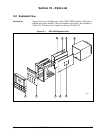
Printed wiring board
identification
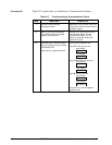
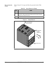
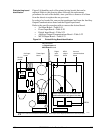
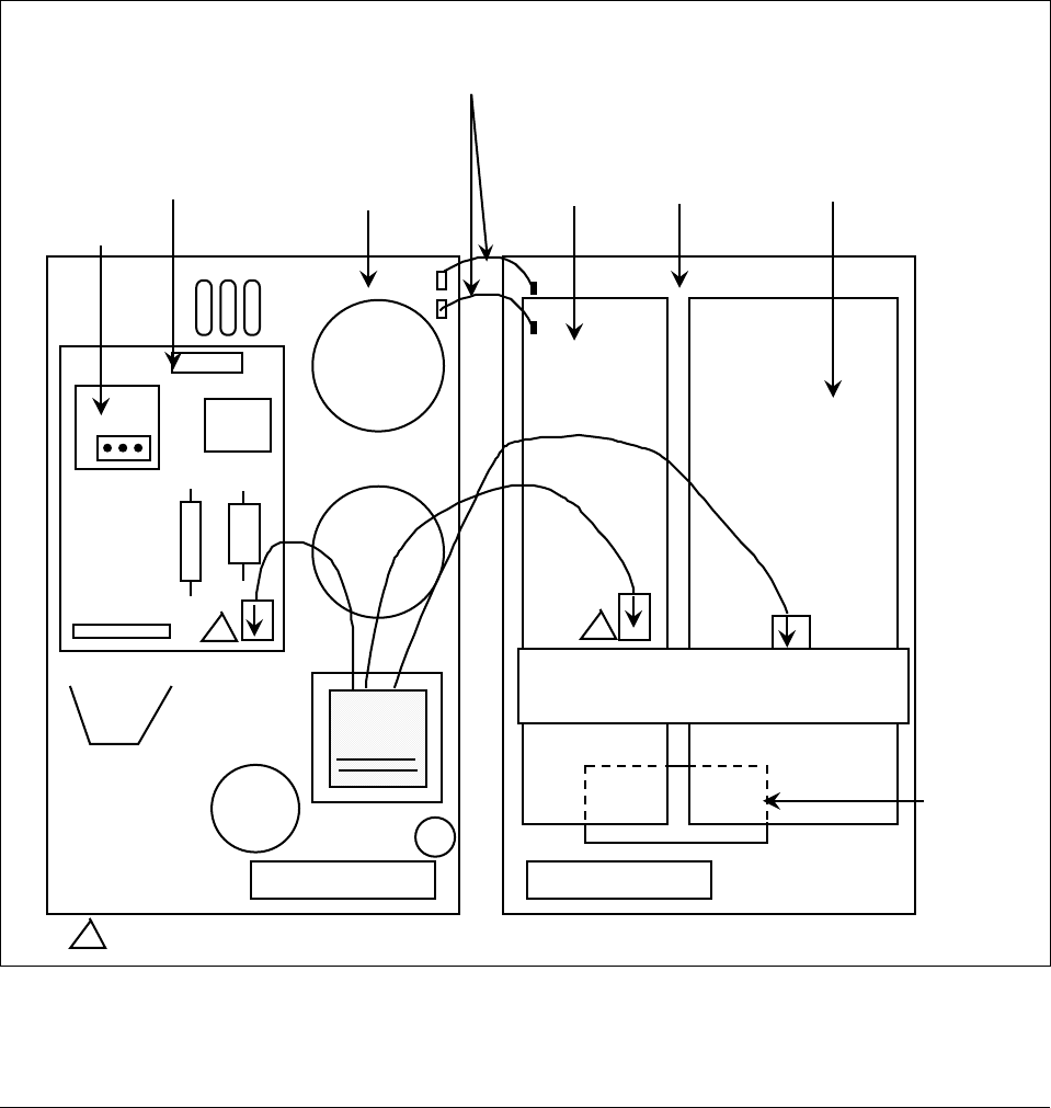
Figure 9-4 identifies each of the printed wiring boards that can be
replaced. Refer to this drawing when following the replacement
procedures for each of the boards, since you have to remove all of them
from the chassis to replace the one you want.
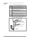
In order to lay boards flat, remove the transformer lead from the Auxiliary
Output/Communications board and the Digital Input board.
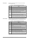
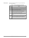
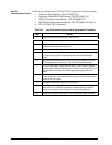
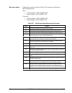
Refer to the specific procedure table to remove the desired board.
• 2nd Input Board—Table 9-19
• Power Input Board—Table 9-20
• Digital Input Board—Table 9-21
• Auxiliary Output/Communications Board—Table 9-22
• MCU/Output Board—Table 9-23
Figure 9-4 Printed Wiring Board Identification
2nd input
board
Power/input
board
WG connectors
on Digital Input and
MCU/Output boards
Digital
input
board
MCU/
output
board
Aux.out/
communications
board
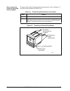
Note: the transformer connectors are
polarized and will only go on one way
1
1
1 2-Pin Transformer connections are interchangeable. Either may be used on Digital Input Board or the second Input Board.
PROM
24279
W1/W2
jumper
W1
W2