


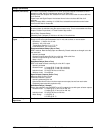
4/00 UDC 3300 Controller Product Manual 17
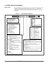
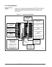
Wiring the controller
Using the information contained in the model number, select the
appropriate wiring diagrams from the figures listed below and wire the
controller accordingly.
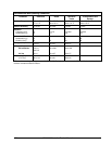
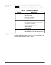
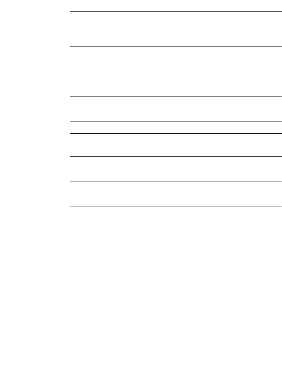
Wiring Requirements Figure
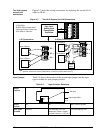
Composite Wiring Diagram 2-4
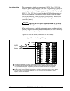
Line Power 90–264 Vac or 24Vac/dc 2-5
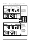
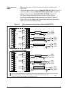
Input #1 and Input #2 Wiring 2-6
Two HLAI Wiring 2-7
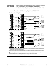
Time Proportional Output
• Electromechanical Relay Output
• Solid State Relay Output
• 10-amp Solid State Relay Output
• Open Collector Output
2-8
2-9
2-10
2-11
Current Output/Universal Output
• Two Current and Two Relay Outputs
• One Current (Auxiliary) and Three Relay Outputs
2-12
2-13
Position Proportional Output 2-14
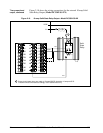
Auxiliary Output Wiring 2-15
Digital Inputs Wiring 2-16
Communications Wiring
• RS422/485/Modbus
• DMCS
2-17
2-18
Transmitter Power for 4-20 mA 2-wire Transmitters
• Open Collector Alarm 2 Output
• Auxiliary Output
2-19
2-20