


4/00 UDC 3300 Controller Product Manual 5
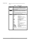
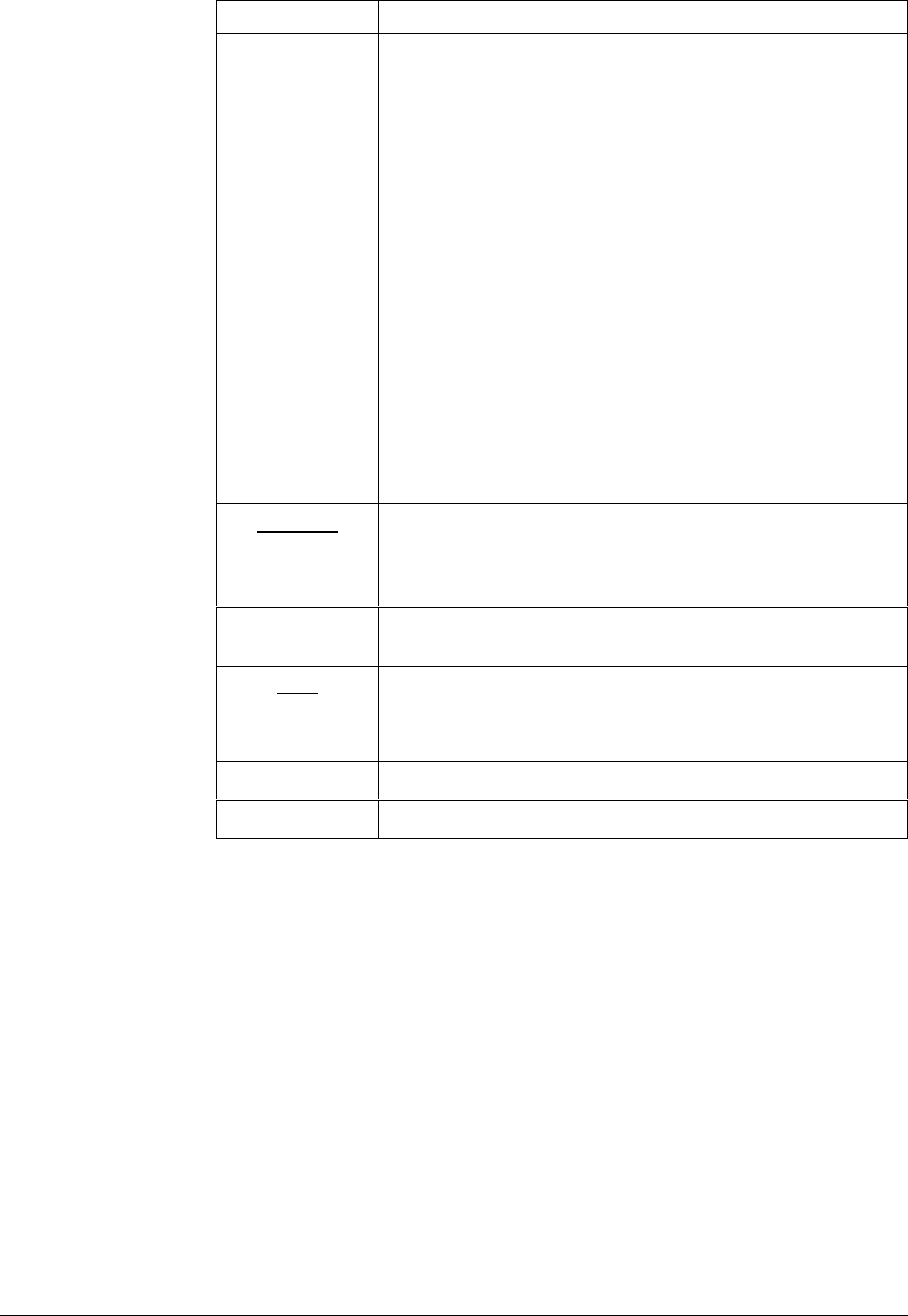
Key Function
LOWER
DISPLAY
1PV = For Cascade or 2 Loops
2PV = For Cascade or 2 Loops
AUX = Auxiliary Output
OC1 = Characterized Output 1
OC2 = Characterized Output 2
SPn = Setpoint Now (for setpoint rate)
• (Sigma) = Current Totalizer Value
BIA = Output Bias/Manual Reset Value
TUNE OFF =
Appears when Limit Cycle tuning is disabled
TUNE RUN = Press ▲ and LOWER DISPLAY to initiate
Limit Cycle tuning.
Display will read TUNE RUN.
ToBEGIN = Reset SP Program to start of first segment
OTI = Internal Loop 1 Output Value is being
displayed (Override has been selected and
Loop 1 is in Automatic mode.)
Note 1: Value can be changed if in manual mode
Note 2: Value can be changed via increment/decrement keys.
Note 3: The selected set can be changed via increment/decrement
keys.
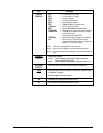
MANUAL
AUTO
• Alternately selects:
AUTO Lower display automatically displays setpoint
value in engineering units.
MAN Lower display automatically indicates output in %.
SETPOINT
SELECT
• Hold key down to cycle through configured setpoints.
RUN
HOLD
• Alternate action switch initiates or holds the Setpoint Ramp
or Setpoint Program.
• Acknowledges a latched alarm 1.
▲
• Increases the selected parameter value.
▼
• Decreases the selected parameter value.